F.2 Configuring the DIP Switches
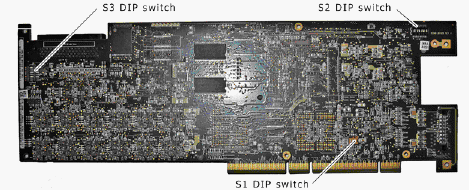
The CG 6565 DIP switches are located on the board, as shown in the following illustration:
Figure F-2 CG 6565 DiP Switches
F.2.1 S3 DIP Switch
The S3 DIP switch controls the H.100 bus termination. By default, all S3 switches are set to OFF (H.100 bus termination disabled). Setting all S3 switches to ON enables H.100 bus termination. Set all S3 switches to ON only for the boards that are on the ends of the H.100 bus.
NOTE:The switches in the S3 DIP switch must be set to either all ON or all OFF.
F.2.2 S2 DIP Switch
Switch 5 in the S2 DIP switch allows you to control if the board LEDs can be off or on. (This is known as the dark office feature.) By default, switch 5 is set to OFF (all LEDs can be on). Setting switch 5 to ON turns off all LEDs on the board unless there is an error.
F.2.3 S1 DIP Switch
The S1 DIP switch sets the mode of the board. By default, the switches set the board to the PCI mode.
Table F-1 S1 Dis Switch Mode Settings