6.2 Creating Security Policies
To begin a security policy:
-
In the Management Console, click > .
-
Specify the name for the new policy, then click to display the Management Console with the Policy toolbar and the Policy tabs displayed.
-
Configure the policy settings using the following tabs (click each link for detailed information about each tab and its options):
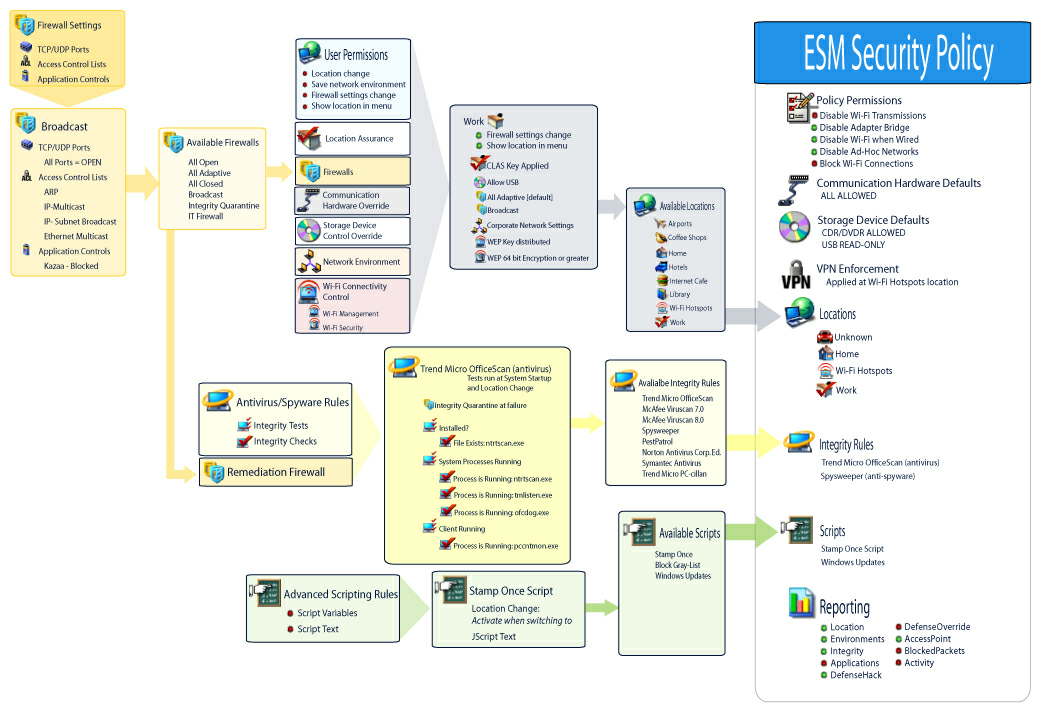
Security policies are built by defining all the Global Settings (default behaviors), then creating and associating existing components for that policy, such as locations, firewalls and integrity rules, and finally establishing compliance reporting for the policy.
The components are created either within a dummy policy or are associated from other policies. It is assumed that for your first few policies you are creating all of the unique locations, firewall settings and integrity rules for the enterprise. These components are stored in the Management Service’s database for possible later use in other policies.
The diagram below shows the components for each level and a resulting policy taken from the selections.
Figure 6-4 ZENworks Endpoint Security Management Security Policy creation process
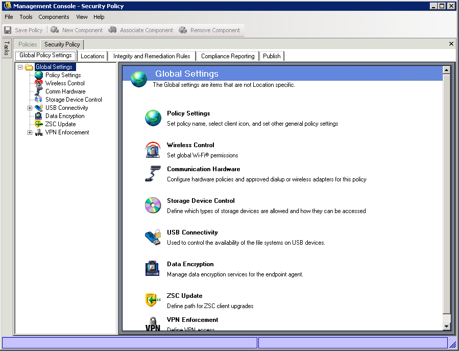
6.2.1 Global Policy Settings
The global policy settings are applied as basic defaults for the policy. To access this control, in the Management Console, click the tab.
Figure 6-5 Global Policy Settings
The following sections contain more information about the settings you can configure on a global basis:
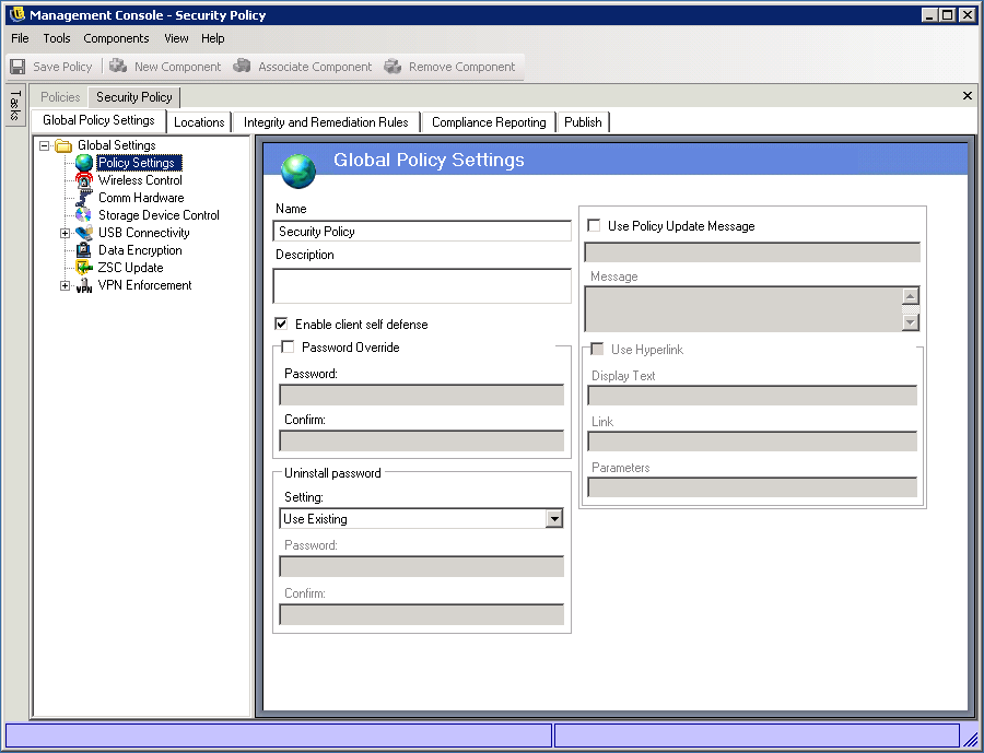
Policy Settings
The primary global settings include:
-
Name and Description: The policy name was specified at the beginning of the policy creation process. You can edit the name or provide a description of the policy.
-
Enable client self defense: Client Self Defense can be enabled or disabled by policy. Leaving this box checked ensures that Client Self Defense is active. Unchecking the box deactivates Client Self Defense for all endpoints using this policy.
-
Password Override: This feature allows an administrator to set a password override that can temporarily disable the policy for a specified period of time. Check the box and enter the password in the provided field. Enter the password again in the confirmation field. Use this password in the Override Password Generator to generate the password key for this policy.
WARNING:It is highly recommended that end users are not given this password, rather the Override Password Generator should be used to generate a temporary key for them.
-
Uninstall Password: We recommend that every Endpoint Security Client be installed with an uninstall password to prevent users from uninstalling the software. This password is normally configured at installation; however, the password can be updated, enabled, or disabled via policy.
-
The default setting is Use Existing, which will not change the uninstall password.
-
Enabled is used to either activate an uninstall password or to change it. Enter the new password and confirm it.
-
Disabled is used to deactivate the uninstall password requirement.
-
-
Use Policy Update Message: You can display a custom user message whenever the policy is updated. Click on the check box, then specify the message information in the provided boxes.
-
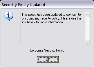
Use Hyperlink: A hyperlink to additional information, corporate policy, or other related information can be included at the bottom of the custom message (see Section 6.3.4, Hyperlinks for more information). The following is an example of the dialog box displayed to the user.
Figure 6-6 Updated Policy Custom Message with Hyperlink
Wireless Control
Wireless Control globally sets adapter connectivity parameters to secure both the endpoint and the network. To access this control, click the tab, then click the icon in the policy tree on the left.
Figure 6-7 Wireless Control Policy
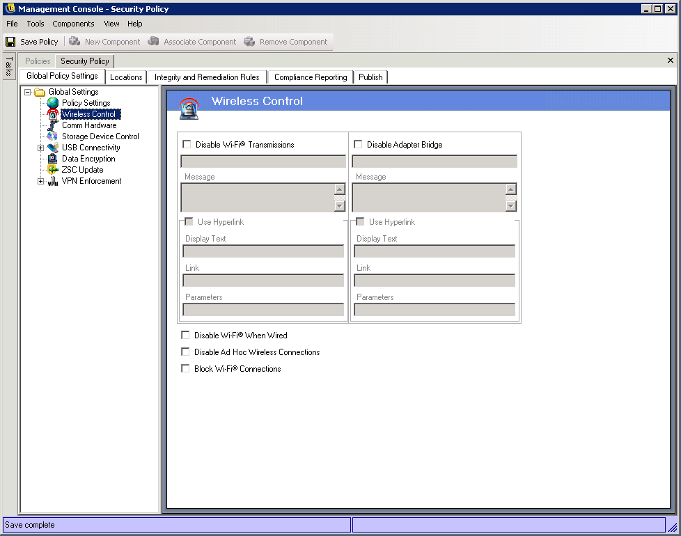
The wireless control settings include the following:
-
Disable Wi-Fi Transmissions: This setting globally disables all Wi-Fi adapters, up to and including complete silencing of a built-in Wi-Fi radio.
You can choose to display a custom user message and hyperlink when the user attempts to activate a Wi-Fi connection. See Section 6.3.3, Custom User Messages for more information.
-
Disable Adapter Bridge: This setting globally disables the networking bridge functionality included with Windows XP, which allows the user to bridge multiple adapters and act as a hub on the network.
You can choose to display a custom user message and hyperlink when the user attempts a Wi-Fi connection. See Section 6.3.3, Custom User Messages for more information.
-
Disable Wi-Fi When Wired: This setting globally disables all Wi-Fi Adapters when the user has a wired (LAN through the NIC) connection.
-
Disable AdHoc Networks: This setting globally disables all AdHoc connectivity; thereby, enforcing Wi-Fi connectivity over a network (for example, via an access point) and restricts all peer-to-peer networking of this type.
-
Block Wi-Fi Connections: This setting globally blocks Wi-Fi connections without silencing the Wi-Fi radio. Use this setting when you want to disable Wi-Fi connection, but want to use access points for location detection. See Section 6.2.2, Locations for more information.
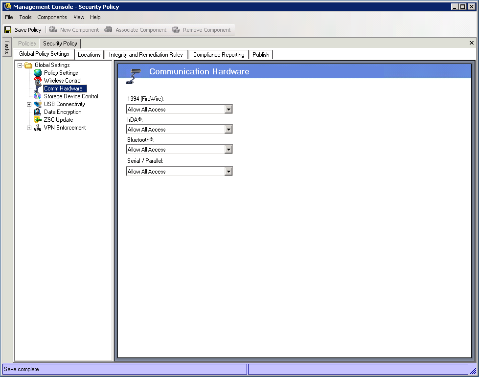
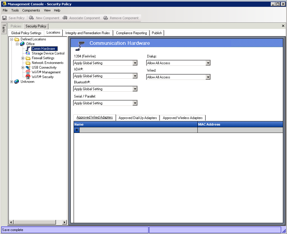
Communication Hardware
Communication hardware controls, by location, which hardware types are permitted a connection within this network environment.
Figure 6-8 Communication Hardware Policy
NOTE:You can set the communication hardware controls globally on the tab or for individual locations on the tab.
To access this control:
To set the communication hardware controls on a global basis, click the tab, expand in the tree, then click .
or
To set the communication hardware controls for a location, click the tab, expand the desired location in the tree, then click . For more information about setting the communication hardware settings for a location, see Communication Hardware.
Select to either allow or disable the global setting for each communication hardware device listed:
-
1394 (FireWire): Controls the FireWire access port on the endpoint.
-
IrDA: Controls the infrared access port on the endpoint.
-
Bluetooth: Controls the Bluetooth access port on the endpoint.
-
Serial/Parallel: Controls serial and parallel port access on the endpoint.
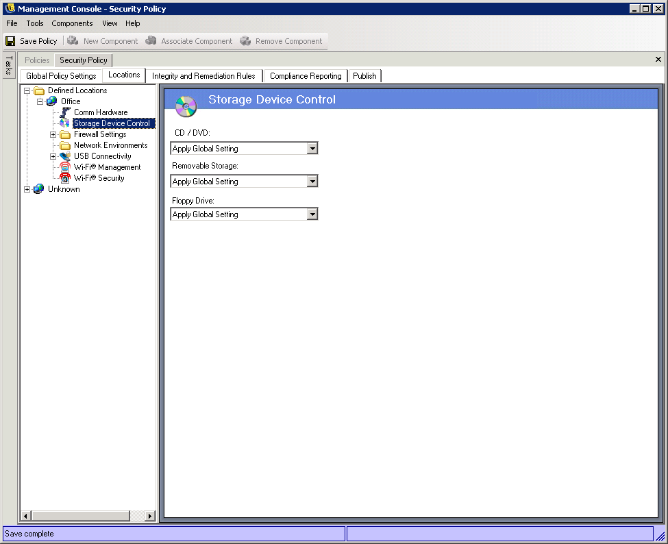
Storage Device Control
Storage device controls set the default storage device settings for the policy, where all external file storage devices are either allowed to read/write files, function in a read-only state, or be fully disabled. When disabled, these devices are rendered unable to retrieve any data from the endpoint; while the hard drive and all network drives remain accessible and operational.
NOTE:You can set the storage device controls globally on the tab or for individual locations on the tab.
To access this control:
To set the storage device controls on a global basis, click the tab, expand in the tree, then click .
or
To set the storage device controls for a location, click the tab, expand the desired location in the tree, then click . For more information, see Communication Hardware.
Figure 6-9 Global Storage Device
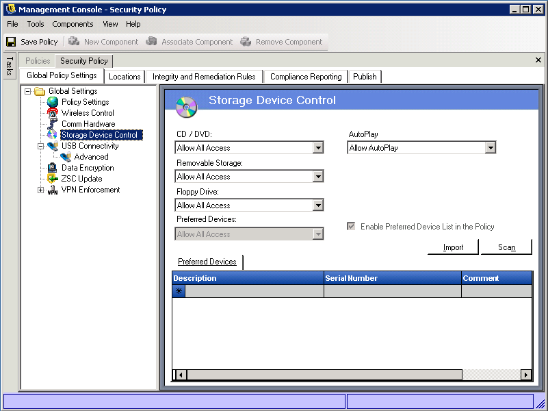
Storage Device Control is differentiated into the following categories:
-
CD/DVD: Controls all devices listed under in Windows Device Manager.
-
Removable Storage: Controls all devices reporting as Removable storage under Disk drives in Windows Device Manager.
-
Floppy Drive: Controls all devices listed under in Windows Device Manager.
-
Preferred Devices: Allows only Removable Storage devices included in the Preferred Devices list. All other devices reporting as removable storage are not allowed. For information about adding preferred devices, see Preferred Devices.
-
AutoPlay: Controls the Windows AutoPlay feature. AutoPlay performs two processes. First, it launches the AutoRun process, which looks for an autorun.inf in the root directory and executes the instructions in the file. Second, it looks for specific content (music, video, and pictures) and launches the appropriate application to display or play the content. Select one of the following options:
-
: Allows the AutoPlay feature, including AutoRun.
-
: Blocks the AutoPlay feature, including AutoRun.
-
: Blocks the AutoRun feature so that autorun.inf instructions are not executed. Launching of applications for music, video and pictures is not blocked.
-
Fixed storage (hard disk drives) and network drives (when available) are always allowed.
To set the policy default for a category, select from the following options:
-
Allow All Access: The device type is allowed by default.
-
Disable All Access: The device type is disallowed. When users attempt to access files on a defined storage device, they receive an error message from the operating system, or the application attempting to access the local storage device, that the action has failed
-
Read-Only Access: The device type is set as Read-Only. When users attempt to write to the device, they receive an error message from the operating system, or the application attempting to access the local storage device, that the action has failed
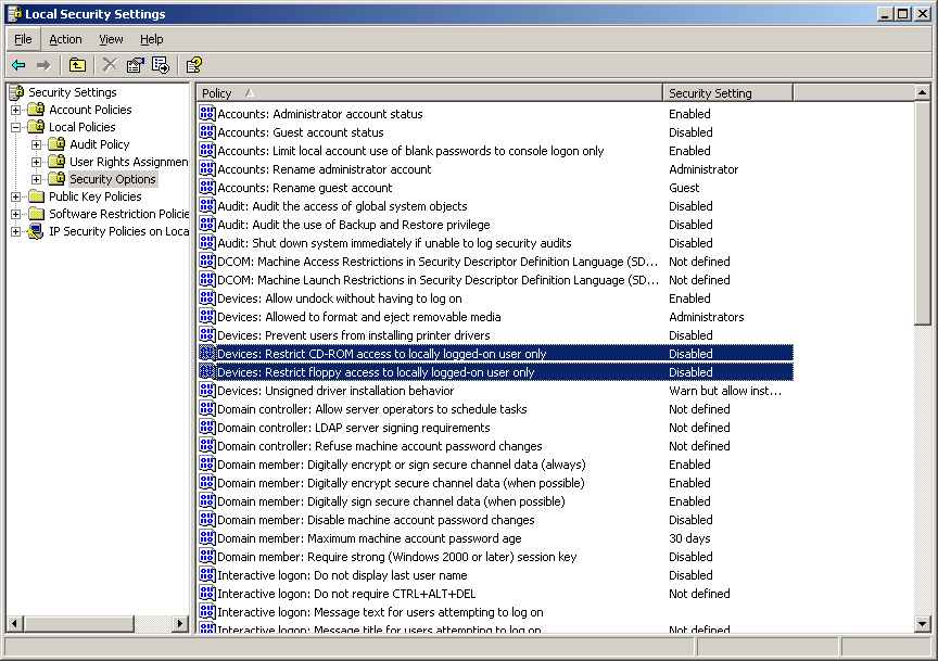
NOTE:If you want to disable CD-ROM drives or floppy drives on a group of endpoints or set them as Read-Only, the Local Security Settings (passed down through a directory service group policy object) must have both and set as . To verify this, open either the group policy object, or open Administrative Tools on a machine. Look in Local Security Settings - Security Options and verify both devices are disabled (see Figure 6-10). Disabled is the default.
Figure 6-10 Verify Local Storage Device Options are set as Disabled
Preferred Devices
Preferred Removable Storage Devices may be optionally entered into a list, permitting only the authorized devices access when the global setting is used at a location. Devices entered into this list must have a serial number.
To add a preferred device:
-
Manually enter the device information. To do so, click a field (, , ) and type the information.
or
Scan the device information. To do so, insert the device into a USB port on the Manangement Console’s machine, then click .
-
Select one of the following settings from the Preferred Devices list. All Removable Storage devices use the same setting:
-
Allow All Access: The devices in the Preferred Devices list are permitted full read/write capability. All other Removable Storage devices are disabled.
-
Read-Only Acess: The devices on the Preferred Devices list are permitted read-only capability. All other Removable Storage devices are disabled.
-
NOTE:Location-based Storage Device Control settings override the global settings. For example, you might define that at the Work location, all external storage devices are permitted, while allowing only the global default at all other locations, limiting users to the devices on the preferred list.
USB Connectivity
All devices that connect via the USB BUS can be allowed or denied by policy. These devices can be scanned into the policy from the USB Device Inventory report or by scanning all devices currently connected to a machine. These devices can be filtered based on manufacturer, product name, serial numbers, type, and so forth.For support purposes, the administrator can configure the policy to accept a set of devices, either by manufacturer type, (for example, all HP devices are allowed), or by product type (all USB-human interface devices [mouse and keyboard] are allowed). Additionally, individual devices can be permitted to prevent non-supported devices from being introduced into the network (for example, no printers are allowed except for this one).
To access this control, click the tab, then click in the policy tree on the left.
Figure 6-11 USB Connectivity page.
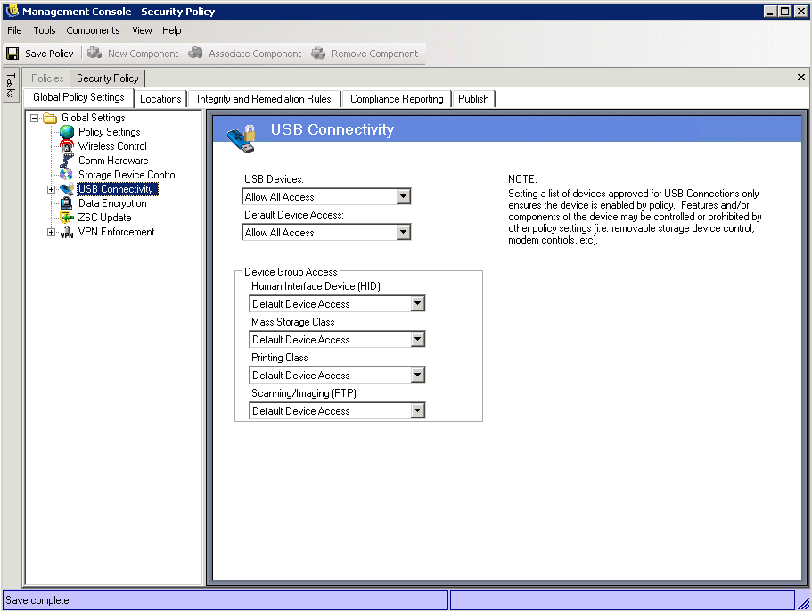
Access is first evaluated based on whether the bus is active or not. This is determined by the setting. If this setting is set to , the device is disabled and evaluation stops. If this setting is set to , the client continues the evaluation and set looking for filter matches. As with many other fields in the ZENworks Management Console, when being set on a location, the value can also be set to and the global value of this field will be used instead.
The client gathers the filters that are applied from the policy, based on the location and global settings.The client will then group the filters based on access into the following groups:
-
Always Block: Always block the device. This setting cannot be overridden.
-
Always Allow: Always allow access unless the device matches an filter.
-
Block: Block access unless the device matches an filter.
-
Allow: Allow access unless the device matches an or a filter.
-
Default Device Access: Give the device the same access level as if no other match is found.
A device is evaluated against each group in the above order (first the group, followed by , and so forth). When a device matches at least one filter in a group, the device's access is set to that level and evaluation stops. If the device is evaluated against all filters, and no match is found, the level is applied.
Device Access set in the area is considered along with all other filters being used at that location. This is done by generating matching filters for each of the grouping when the policy is published to the client. These filters are as follows:
Advanced
In most situations, the four device groups listed on the USB Connectivity page (Human Interface Device, Mass Storage Class, Printing Class, and Scanning/Imaging) are sufficient to allow or deny access to most USB devices. If you have devices that do not register in one of these groups, you can configure settings on the USB Connectivity Advanced page. You can also use the settings on the Advanced page to provide whitelist access to certain devices even though they might be denied access because of the settings on the USB Connectivity page.
To access the Advanced USB Connectivity options, click the plus sign next to in the tree, then click . You can use the USB Device Audit report as a means of getting all the information you could potentially use on the USB Connectivity Control Advanced page.
Figure 6-12 USB Connectivity Advanced page.
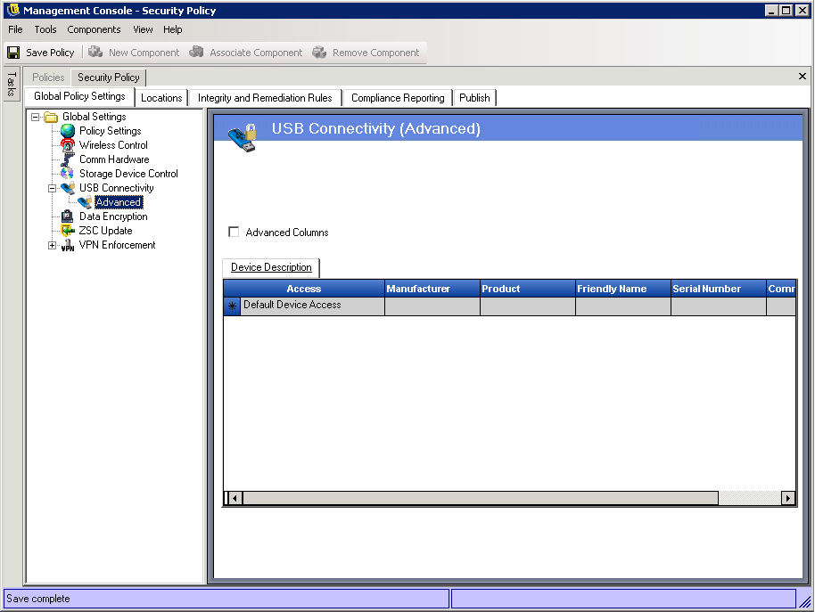
To add a device to the list, fill in the following fields:
-
Access: Select an access level:
-
Always Block: Always block the device. This setting cannot be overridden.
-
Always Allow: Always allow access unless the device matches an filter.
-
Block: Block access unless the device matches an filter.
-
Allow: Allow access unless the device matches an or a filter.
-
Default Device Access: Give the device the same access level as if no other match is found.
-
-
Manufacturer: Click the column then type the name of the manufacturer you want to include in the filter (Canon, for example).
-
Product: Click the column then type the name of the product you want to include in the filter.
-
Friendly Name: Click the column then type the friendly name of the device you want to include in the filter.
-
Serial Number: Click the column then type the serial number of the device you want to include in the filter.
-
Comment: Click the column then type the comment you want to include in the filter (Canon, for example).
You can click the box to add the following columns: , , and .
A device makes available a set of attributes to the OS. These attributes are matched by the client to the fields required by a filter. All fields in the filter must match an attribute provided by the device in order to have a match. If the device does not provide an attribute or field that is required by the filter, that filter fails to match.
For example, suppose a device provides the following attributes: Manufacture: Acme Class: 8, Serial Number: "1234".
The filter: Class == 8 would match this device. The filter: Product == "Acme" would not match because the device did not provide a Product attribute to the OS.
The following fields are sub-string matched: Manufacturer, Product, and Friendly Name. All other fields are exact matches.
As a matter of interest, USB serial number(SN) field by spec. is only unique when considered when specifying the following fields along with the SN: USB Version, Vendor ID, Production ID, and BCD Device.
Current valid values for USB version in decimal are: 512 - USB 2.0, 272 - USB 1.1, 256 - USB 1.0.
Data Encryption
Data Encryption determines whether file encryption is enforced on the endpoint and what type of encryption is available. Data can be encrypted to permit file sharing (with password protection) or can set encrypted data to be read-only on computers running the Storage Encryption Solution.
NOTE:Encryption is supported only on Windows XP SP2. The encryption portion of the security policy is ignored on devices that do not meet this OS requirement.
To access this control, click the tab, then click in the policy tree on the left.
Figure 6-13 Data Encryption controls
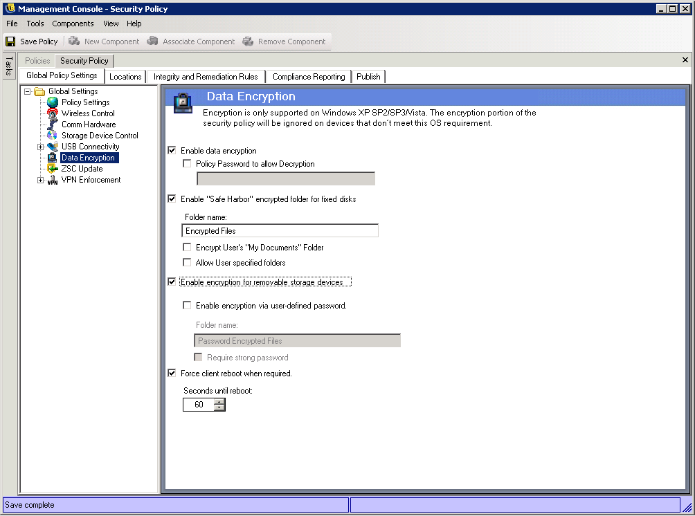
To activate the individual controls, click the check box.
NOTE:Encryption keys are distributed to all machines that receive policies from the Policy Distribution Service, regardless of whether data encryption is activated or not. However, this control instructs the Endpoint Security Client to activate its encryption drivers, which allows users to read files sent to them without requiring the File Decryption Utility. See Section 9.1, Using the ZENworks File Decryption Utility for more details.
Determine what levels of encryption are permitted by this policy:
-
Policy password to allow decryption: Entering a password here to require all users using this policy to enter this password prior to decrypting any encrypted files stored in their Safe Harbor folders.
This is an optional setting, leave blank to not require the password.
-
Enable “Safe Harbor” encrypted folder for fixed disks: Generates a folder at the root of all volumes on the endpoint, named Encryption Protected Files. All files placed in this folder are encrypted and managed by the Endpoint Security Client. Data placed in this folder is automatically encrypted and can only be accessed by authorized users on this machine.
The folder name can be changed by clicking in the field, selecting the current text, and entering the name you desire.
-
Encrypt User’s “My Documents” Folder: Select this option to encrypt all files in the user’s My Documents folder. As with the Safe Harbor folder, data placed in this folder is automatically encrypted and can only be accessed by authorized users on this machine.
-
Allow user specified folders: Select this option to allow users to select which folders on their computer are encrypted. This is for local folders only; no removable storage devices nor network drives can be encrypted.
WARNING:Before disabling data encryption, ensure that all data stored in these folders has been extracted by the user and stored in another location.
-
-
Enable encryption for removable storage devices: All data written to removable storage devices from an endpoint protected by this policy is encrypted. Users with this policy on their machines are able to read the data; therefore, file sharing via removable storage device within a policy group is available. Users outside this policy group are not able to read the files encrypted on the drive, and will only be able to access files within the Password Encrypted Files folder (if activated) with a provided password.
-
Enable encryption via user-defined password: This setting gives the user the ability to store files in a Password Encrypted Files folder on the removable storage device (this folder will be generated automatically when this setting is applied).
When a user adds files to this folder, the files are encrypted with a password that the user supplies. The user can then access the files from any device that is not running the Security client. To decrypt the files, the user needs the ZENworks File Decryption utility and the encryption password. You must supply this utility to the user; it is not part of the Security client (see Section 9.1, Using the ZENworks File Decryption Utility).
For example, assume that a user is working on encrypted files at work. The user wants to take the files home to work on them, but the home computer does not have the Security client installed. The user copies the files to the Password Encrypted Files folder on a USB thumb drive, takes the files home, then accesses them using the ZENworks File Decryption utility you provided.
If desired, you can change the default folder name (Password Encrypted Files) to another name.
-
Require strong password: This setting forces the user to set a strong password for the Password Encrypted Files folder. A strong password requires the following:
-
seven or more characters
-
at least one of each of the four types of characters:
-
uppercase letters from A to Z
-
lowercase letters from a to z
-
numbers from 0 to 9
-
at least one special character ~!@#$%^&*()+{}[]:;<>?,./
-
For example: y9G@wb?
-
WARNING:Before disabling data encryption, ensure that all data stored on removable storage devices has been extracted by the user and stored in another location.
-
-
Force client reboot when required: When encryption is added to a policy, it does not become active until the endpoint is rebooted. This setting forces the required reboot by displaying a countdown timer, warning the user that the machine will reboot in the specified number of seconds. The user has that amount of time to save work before the machine reboots.
Reboots are required when encryption is first activated in a policy, and again when either “Safe Harbor” or removable storage encryption is activated (if activated separately from encryption activation). For example, when an encryption policy is applied for the first time, two reboots are required: one reboot to initialize the drivers and another reboot to put any safe harbors into encryption. If additional safe harbors are subsequently selected after the policy has been applied, only one reboot is required to put the safe harbor into policy.
ZSC Update
Patches to repair any minor defects in the Endpoint Security Client are made available with regular ZENworks Endpoint Security Management updates. Rather than providing a new installer, which needs to be distributed through MSI to all endpoints, ZENworks Security Client Update allows the administrator to dedicate a zone on the network that distributes update patches to end users when they associate to that network environment.
To access this control, click the tab, then click in the policy tree on the left.
Figure 6-14 ZSC Update
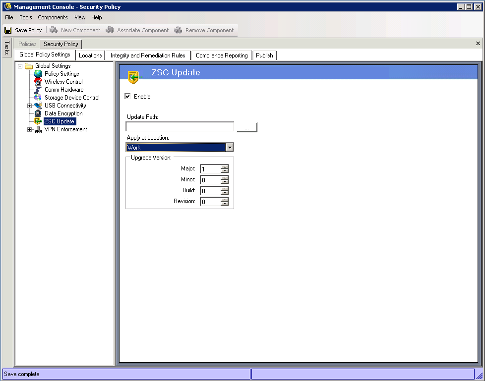
To facilitate simple and secure distribution of these patches to all Endpoint Security Client users:
-
Check Enable to activate the screen and the rule.
-
Specify the location where the Endpoint Security Client looks for the updates. Due to the recommendations in the next step, the location associated with the enterprise environment (i.e.: the "Work" location) is the recommended candidate.
-
Enter the URI where the patch has been stored. This needs to point to the patch file, which can be either the setup.exe file for the Endpoint Security Client, or an MSI file created from the .exe file). For security purposes, it is recommended that these files be stored on a secure server behind the corporate firewall.
-
Enter the version information for this file in the provided fields. Version information is found by installing the Endpoint Security Client and opening the About screen (see the ZENworks Endpoint Security Management Installation Guide for details). The version number for STEngine.exe is the version number you want to use in the fields.
Each time the user enters the assigned location, the Endpoint Security Client checks the URI for an update that matches that version number. If an update is available, the Endpoint Security Client downloads and installs it.
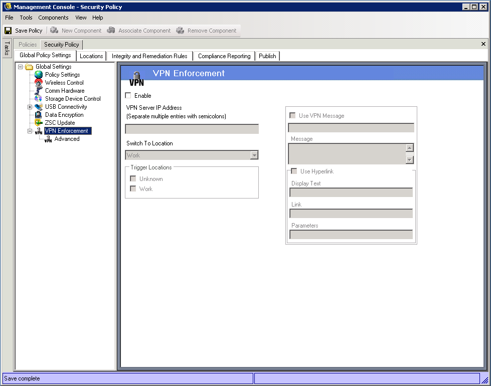
VPN Enforcement
This rule enforces the use of either an SSL or a client-based VPN (Virtual Private Network). This rule is typically applied at wireless hotspots, allowing the user to associate and connect to the public network, at which time the rule attempts to make the VPN connection, then switches the user to a defined location and firewall setting. All parameters are at the discretion of the administrator. All parameters override existing policy settings. The VPN-Enforcement component requires the user be connected to a network prior to launching.
NOTE:This feature is only available in the ZENworks Endpoint Security Management installation, and cannot be used for UWS security policies.
To access this control, click the tab, then click in the policy tree on the left.
Figure 6-15 Basic VPN Enforcement
To use the VPN Enforcement rule, at least two locations must exist.
To add VPN enforcement to a new or existing security policy:
-
Select to activate the screen and the rule.
-
Specify the IP addresses for the VPN Server in the provided field. If multiple addresses are specified, separate each with a semi-colon (for example: 10.64.123.5;66.744.82.36).
-
Select the Switch To Location from the drop-down list. The Endpoint Security Client switches to this location after the VPN authenticates.
The Switch To location is the location the Endpoint Security Client switches to when the VPN is activated. It is recommended that this location contain some restrictions, and only a single restrictive firewall setting as its default.
The firewall setting, which closes all TCP/UDP ports, is recommend for strict VPN enforcement. This setting prevents any unauthorized networking, while the VPN IP address acts as an ACL to the VPN server, and permits network connectivity.
-
Select the Trigger locations where the VPN enforcement rule is applied. For strict VPN enforcement, it is recommended the default Unknown location be used for this policy. After the network has authenticated, the VPN rule activates and switches to the assigned Switch To Location.
NOTE:The location switch occurs before the VPN connection, after the network has authenticated.
-
Enter a Custom User Message to display when the VPN has authenticated to the network. For non-client VPNs, this should be suffiClient.
For VPNs with a client, include a hyperlink that points to the VPN Client.
Example: C:\Program Files\Cisco Systems\VPN Client\ipsecdialer.exe
This link launches the application, but the user stills need to log in. A switch can be entered into the Parameters field, or a batch file could be created and pointed to, rather than the client executable).
NOTE:VPN clients that generate virtual adapters (for example, Cisco Systems* VPN Client 4.0) display the: "Policy Has Been Updated" message. The Policy has not been updated, the Endpoint Security Client is simply comparing the virtual adapter to any adapter restrictions in the current policy.
The standard VPN Enforcement settings described above make VPN connectivity an option. Users are granted connectivity to the current network whether they launch their VPN or not. For stricter enforcement, see Advanced VPN Settings below.
Advanced VPN Settings
Advanced VPN controls are used to set Authentication Timeouts to secure against VPN failure, connect commands for client-based VPNs, and use Adapter controls to control the adapters permitted VPN access.
To access this control, click the tab, click the “+” symbol next to , then click Advanced in the policy tree on the left.
Figure 6-16 Advanced VPN Enforcement
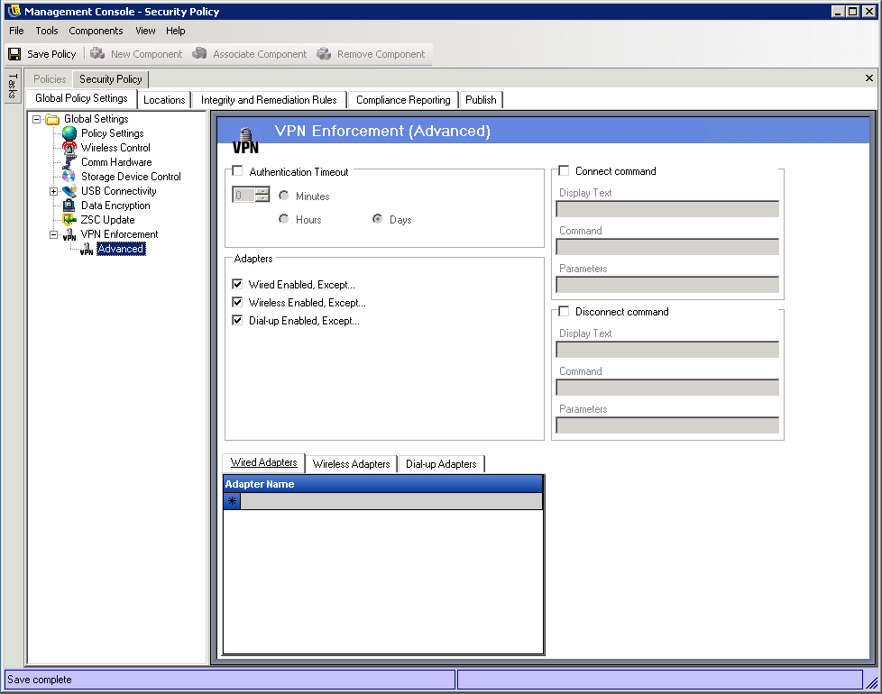
The following advanced VPN enforcement settings can be configured:
Authentication Timeout: Administrators can place the endpoint in a secured firewall setting (the firewall setting) to secure against any failure of VPN connectivity. The is the amount of time the Endpoint Security Client waits to gain authentication to the VPN server. It is recommended that this parameter be set above 1 minute to allow authentication over slower connections.
Connect/Disconnect Commands: When using the Authentication timer, the and commands control client-based VPN activation. Specify the location of the VPN client and the required switches in the fields. The Disconnect command is optional, and provides for VPN clients that require that the user disconnects before logging off of the network.
NOTE:VPN clients that generate virtual adapters (for example, Cisco Systems VPN Client 4.0) display the: "Policy Has Been Updated" message, and may switch away from the current location temporarily. The Policy has not been updated, the Endpoint Security Client is simply comparing the virtual adapter to any adapter restrictions in the current policy. It is recommended that when running VPN clients of this type that the Disconnect command hyperlink not be used.
Adapters: This is essentially a mini Adapter policy specific to the VPN Enforcement.
If an adapter is checked (changing it to Enabled, Except), those adapters (Wireless being specific to card type) are permitted connectivity to the VPN.
Adapters entered into the exception lists below, are denied connectivity to the VPN, while all others of that type will be given connectivity.
If an adapter is not checked (Disabled, Except), then only the adapters entered into the exception list are permitted to connect to the VPN; all others are denied connectivity.
This control can be used for adapters incompatible to the VPN, for example, or adapters not supported by the IT department.
This rule overrides the adapter policy set for the switch-to location.
6.2.2 Locations
Locations are rule-groups assigned to network environments. These environments can be set in the policy (see Section 6.3.6, Network Environments), or by the user, when permitted. Each location can be given unique security settings, denying access to certain kinds of networking and hardware in more hostile network environments, and granting broader access within trusted environments.
To access Location controls, click the tab.
Figure 6-17 Location Settings
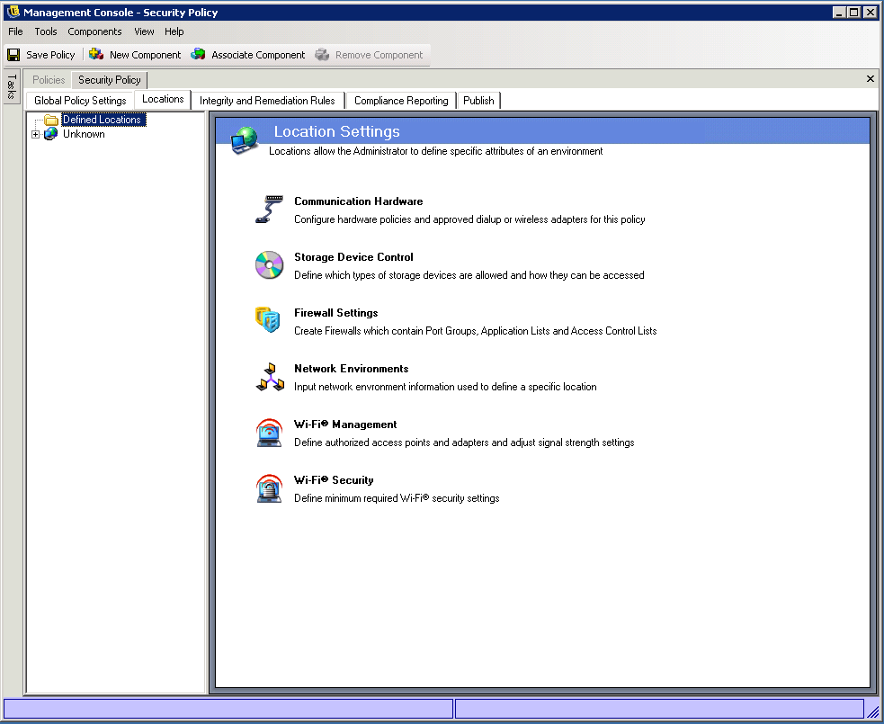
The following sections contain more information:
About Locations
The following types of locations can be configured:
The Unknown Location: All policies have a default Unknown location. This is the location the Endpoint Security Client switches users to when they leave a known network environment. This Unknown location is unique for each policy and is not available as a shared component. Network Environments cannot be set nor saved for this location.
To access the Unknown Location controls, click the tab, then click the location in the policy tree on the left.
Defined Locations: Defined locations can be created for the policy, or existing locations (those created for other policies) can be associated.
To create a new location:
-
Click , then click the button on the toolbar.
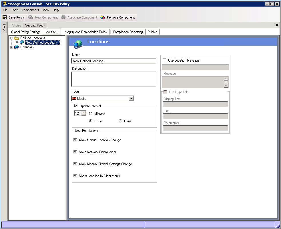
-
Name the location and provide a description.
-
Define the location settings (see below).
-
Click .
To associate an existing location:
-
Click , then click the button on the toolbar.
-
Select the desired locations from the list.
-
Edit the settings, if desired.
NOTE:Changing the settings in a shared component will affect all other instances of this same component. Use the command to view all other policies associated with this component.
-
Click .
It is recommended that multiple defined locations (beyond simple Work and Unknown locations) be defined in the policy to provide users with varying security permissions when they connect outside the enterprise firewall. Keeping the location names simple (for example, Coffee Shops, Airports, Home) and providing a visual cue through the location's Taskbar icon, which helps users easily switch to the appropriate security settings required for each network environment.
Communication Hardware
Communication hardware controls, by location, which hardware types are permitted a connection within this network environment.
NOTE:You can set the communication hardware controls globally on the tab or for individual locations on the tab.
To access this control:
To set the communication hardware controls for a location, click the tab, expand the desired location in the tree, then click .
or
To set the communication hardware controls on a global basis, click the tab, expand in the tree, then click . For more information, see Communication Hardware.
Figure 6-18 Location Communication Hardware Control
To configure the settings:
-
For each communication hardware type listed below, select , , or :
-
1394 (FireWire): Controls the FireWire access port on the endpoint.
-
IrDA: Controls the infrared access port on the endpoint.
-
Bluetooth: Controls the Bluetooth access port on the endpoint.
-
Serial/Parallel: Controls serial and parallel port access on the endpoint.
-
Dialup: Controls modem connectivity by location. This option is not available when configuring communication hardware settings on a global basis using the tab. If you want to limit access to specific modems, set this option to and then add the approved modems to the list.
-
Wired: Controls LAN card connectivity by location. This option is not available when configuring communication hardware settings on a global basis using the tab. If you want to limit access to specific wired adapters, set this option to and then add the approved adapters to the list.
-
-
(Optional) If you selected for the or settings and you want to limit the adapters that are allowed, add the approved adapters to the appropriate list ( or .
Partial adapter names are permitted. Adapter names are limited to 50 characters and are case sensitive. Only the adapters included in the list are allowed; all other adapters are blocked.
-
(Optional) If you have enabled Wi-Fi (see Wi-Fi Management) and you want to limit the wireless adapters that are allowed, add the approved adapters to the list.
Partial adapter names are permitted. Adapter names are limited to 50 characters and are case sensitive. Only the adapters included in the list are allowed; all other adapters are blocked.
If the endpoint is in a location that defines only a Wi-Fi access point’s SSID as the network identification(see Wi-Fi Management) , the Endpoint Security Client switches to that location before disabling the unauthorized adapter. A password override should be used to provide a manual location switch if this occurs.
The Endpoint Security Client receives notification whenever a network device is installed in the system and determines if the device is approved. If it is not approved, the solution disables the device driver, which renders this new device unusable, and notifies the user of the situation.
When a new unapproved adapter first installs its drivers on the endpoint (via PCMCIA or USB), the adapter displays as enabled in Windows Device Manager until the system is rebooted, though all network connectivity is blocked.
Storage Device Control
Storage device controls set the default storage device settings for the policy, where all external file storage devices are either allowed to read/write files, function in a read-only state, or be fully disabled. When disabled, these devices are rendered unable to retrieve any data from the endpoint; while the hard drive and all network drives remain accessible and operational.
NOTE:You can set the storage device controls globally on the tab or for individual locations on the tab.
To access this control:
To set the storage device controls for a location, click the tab, expand the desired location in the tree, then click .
or
To set the storage device controls on a global basis, click the tab, expand in the tree, then click . For more information, see Storage Device Control.
Figure 6-19 Location Storage Device Control
Storage Device Control is differentiated into the following categories:
-
CD/DVD: Controls all devices listed under in Windows Device Manager.
-
Removable Storage: Controls all devices reporting as Removable storage under Disk drives in Windows Device Manager.
-
Floppy Drive: Controls all devices listed under in Windows Device Manager.
Fixed storage (hard disk drives) and network drives (when available) are always allowed.
To set the policy default for storage devices, select the global setting for both types from the drop-down lists:
-
Apply Global Setting: Use the setting configured in the global Storage Device Control policy.
-
Allow All Access: The device type is allowed by default.
-
Disable All Access: The device type is disallowed. When users attempt to access files on a defined storage device, they receive an error message from the operating system, or the application attempting to access the local storage device, that the action has failed
-
Read-Only Access: The device type is set as Read-Only. When users attempt to write to the device, they receive an error message from the operating system, or the application attempting to access the local storage device, that the action has failed
NOTE:If you want to disable CD-ROM drives or floppy drives on a group of endpoints or set them as Read-Only, the Local Security Settings (passed down through a directory service group policy object) must have both Devices: Restrict CD-ROM access to locally logged-on user only and Devices: Restrict floppy access to locally logged-on user only set as Disabled. To verify this, open either the group policy object, or open Administrative Tools on a machine. Look in Local Security Settings - Security Options and verify both devices are disabled (see Figure 6-10). Disabled is the default.
Figure 6-20 Verify Local Storage Device Options are set as Disabled
Wi-Fi Management
Wi-Fi management allows the administrator to create Access Point lists. The wireless access points entered into these lists determine which access points the endpoint is permitted and not permitted to connect to within the location, and which access points it's permitted to see in the Microsoft Zero Configuration Manager (Zero Config). Third-party wireless configuration managers are not supported with this functionality. If no access points are entered, all access points are available to the endpoint.
To access this control, click the tab, then click in the policy tree on the left.
Figure 6-21 Location Wi-Fi Management
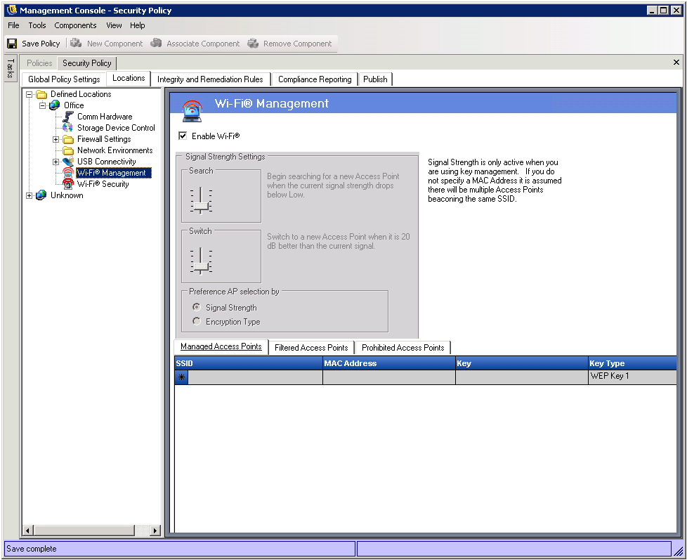
Entering access points into the Managed Access Points list turns off Zero Config and forces the endpoint to connect only to the access points listed when they're available. If the Managed access points are not available, the Endpoint Security Client falls back to the Filtered Access Point List. Access points entered into Prohibited Access Points never display in Zero Config.
NOTE:The access point list is only supported on the Windows XP operating system. Prior to deploying an access point list, it is recommended all endpoints clear the preferred networks list out of Zero Config.
The following sections contain more information:
Wi-Fi Signal Strength Settings
When more than one WEP-managed access point is defined in the Managed Access Points list (see Managed Access Points), the signal strength switching for the Wi-Fi adapter can be set. The signal strength thresholds can be adjusted by location to determine when the Endpoint Security Client searches for, discards, and switches to another access point defined in the list.
Figure 6-22 Signal Strength Control
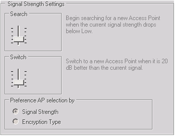
The following settings can be adjusted above or below the current defaults:
-
Search: When this signal strength level is reached, the Endpoint Security Client begins to search for a new access point to connect to. The default setting is Low [-70 dB].
-
Switch: In order for the Endpoint Security Client to connect to a new access point, that access point must broadcast at the designated signal strength level above the current connection. The default setting is +20 dB.
The signal strength thresholds are determined by the amount of power (in dB) reported through the computer’s miniport driver. As each Wi-Fi card and radio may treat the dB signals differently for their Received Signal Strength Indication (RSSI) the numbers vary from adapter to adapter.
The default numbers associated with the defined thresholds in the Management Console are generic for most Wi-Fi adapters. It is recommended you research your Wi-Fi adapter's RSSI values to input an accurate level. The Novell values are:
Although the above signal strength names match those used by the Microsoft Zero Configuration Service, the thresholds may not match. Zero Config determines its values based on the Signal to Noise Ratio (SNR) and not solely on the dB value reported from RSSI. For example, if a Wi-Fi adapter were receiving a signal at -54 dB and had a noise level of -22 dB, the SNR would report as 32dB (-54 - -22=32), which on the Zero Configuration scale would translate as Excellent signal strength, even though on the Novell scale, the -54 dB signal (if reported that way through the miniport driver, possibly reported lower) would indicate a Very Good signal strength.
It's important to note that the end user never sees the Novell signal strength thresholds; this information is merely provided to show the difference between what the user may see through Zero Config and what is actually occurring behind the scenes.
Because both signal strength and encryption type (see Wi-Fi Security) are used to determine the order in which access points are attempted, you must select the preferred method. For example, if signal strength is the preference, then the strongest signal is given the preference when connecting. If WEP 64 is the encryption requirement and encryption is the preference, then access points with the highest encryption strength are given preference over all others.
Managed Access Points
ZENworks Endpoint Security Management provides a simple process to automatically distribute and apply Wired Equivalent Privacy (WEP) keys without user intervention (bypassing and shutting down the Microsoft Zero Configuration manager), and protects the integrity of the keys by not passing them in the clear over an e-mail or a written memo. In fact, the end user never needs to know the key to automatically connect to the access point. This helps prevent possible re-distribution of the keys to unauthorized users.
Due to the inherent security vulnerabilities of Shared WEP Key Authentication, Novell supports only Open WEP Key Authentication. With Shared Authentication the client/AP key validation process sends both a clear text and encrypted version of a challenge phrase that is easily sniffed wirelessly. This can give a hacker both the clear and encrypted versions of a phrase. Once they have this information, cracking the key becomes trivial.
Figure 6-23 Managed Access Points Control
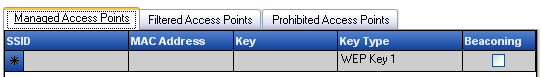
Enter the following information for each access point:
-
SSID: Identify the SSID number. The SSID number is case sensitive.
-
MAC Address: Identify the MAC Address (recommended, due to the commonality among SSIDs. If not specified, it is assumed there are multiple access points beaconing the same SSID number).
-
Key: Specify the WEP key for the access point (either 10 or 26 hexadecimal characters).
-
Key Type: Identify the encryption key index by selecting the appropriate level from the drop-down list.
-
Beaconing: Check if the defined access point is currently broadcasting its SSID. Leave un-checked if this is a non-beaconing access point.
The Endpoint Security Client attempts to first connect to each beaconing access point listed in the policy. If no beaconing access is located, the Endpoint Security Client then attempts to connect to any non-beaconing access points (identified by SSID) listed in the policy.
When one or more access points are defined in the list, the Signal Strength switching for the Wi-Fi adapter can be set (see Wi-Fi Signal Strength Settings).
Filtered Access Points
Access points entered into the list are the only access points that display in Zero Config; this prevents an endpoint from connecting to unauthorized access points.
Figure 6-24 Filtered Access Points Control
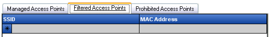
Enter the following information for each access point:
-
SSID: Identify the SSID number. The SSID number is case sensitive.
-
MAC Address: Identify the MAC Address (recommended, due to the commonality among SSIDs. If not specified, it is assumed there will be multiple access points beaconing the same SSID).
Prohibited Access Points
Access points entered into the list do not display in Zero Config, nor will the endpoint be permitted to connect to them.
Figure 6-25 Prohibited Access Points Control
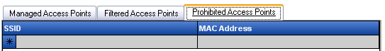
Enter the following information for each access point:
-
SSID: Identify the SSID number. The SSID number is case sensitive.
-
MAC Address: Identify the MAC Address (recommended, due to the commonality among SSIDs. If not specified, it is assumed there will be multiple access points beaconing the same SSID).
Wi-Fi Security
If Wi-Fi Communication Hardware (Wi-Fi adapter PCMCIA or other cards, and built-in Wi-Fi radios) is globally permitted (see Wireless Control), additional settings can be applied to the adapter at this location.
To access this control, click the tab, then click in the policy tree on the left.
Figure 6-26 Location Wi-Fi Security
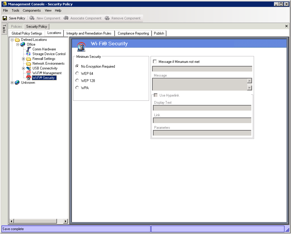
The Wi-Fi adapter can be set to communicate only with access points with a specific level of encryption or greater in a given location.
For example, if a WPA configuration of access points were deployed in a branch office, the adapter can be restricted to only communicate with access points with a level of WEP 128 encryption or greater, thus preventing it from accidentally associating with rogue, non-secure access points.
It is recommended a custom user message be written when the setting is placed above .
A preference can be set to connect to access points by order of encryption level or by signal strength when two or more access points are entered into the and lists. The level selected enforces connectivity with access points that meet the minimum encryption requirement or greater.
For example, if WEP 64 is the encryption requirement and encryption is the preference, then access points with the highest encryption strength are given preference over all others. If signal strength is the preference, then the strongest signal is given the preference when connecting.
6.2.3 Integrity and Remediation Rules
ZENworks Endpoint Security Management provides the ability to verify that required software is running on the endpoint and provides instant remediation procedures if the verification fails.
The following sections contain more information:
Antivirus/Spyware Rules
Antivirus/Spyware Rules verify that designated antivirus or spyware software on the endpoint is running and up to date. Tests are run to determine if the software is running and if the version is up-to-date. Success in both checks allow switching to any defined locations. Failure of either test could result in any or all of the following actions (defined by the administrator):
-
A report is sent to the Reporting Service.
-
A custom user message is displayed, with an optional launch link that provides information on how to fix the rule violation.
-
The user is switched to a Quarantined State, which limits the user's network access and disallows certain programs from accessing the network to prevent the user from further infecting the network.
After endpoints are determined compliant by a follow-up test, security settings automatically return to their original state.
NOTE:This feature is only available in the ZENworks Endpoint Security Management installation, and cannot be used for UWS security policies.
To access this control, click the tab, then click in the policy tree on the left.
Figure 6-27 Antivirus/Spyware Integrity rules
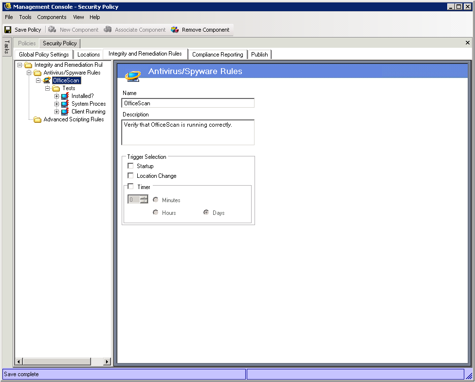
Custom tests for software not on the default list can be created. A single test can be created to run checks for one or more software pieces within the same rule. Each set of Process Running and File Exists checks have their own success/failure results.
To create a new antivirus/spyware rule:
-
Select from the components tree, then click .
-
Click .
-
Name the rule and provide a description.
-
Select the trigger for the rule:
-
Startup: Run tests at system startup.
-
Location Change: Run the tests whenever the Endpoint Security Client switches to a new location.
-
Timer: Run integrity tests on a defined schedule by the minute, hour, or day.
-
-
Click .
-
Define the integrity tests.
To associate existing Antivirus/Spyware Rules:
-
Select , then click .
-
Select the desired rules from the list.
-
If desired, you can redefine the tests, checks, and results.
NOTE:Changing the settings in a shared component affects all other instances of this same component. Use the command to view all other policies associated with this component.
-
Click .
Integrity tests and checks are automatically included and can be edited as necessary.
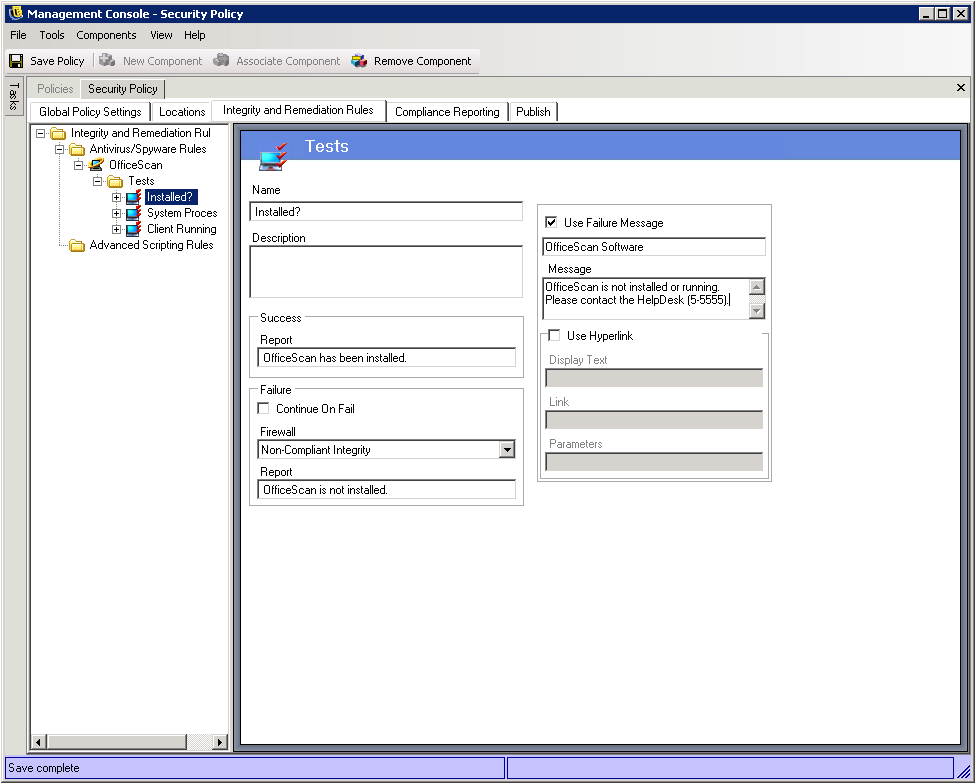
Integrity Tests
Each integrity test can run two checks, and . Each test has its own success and fail results.
Figure 6-28 Integrity Tests
All defined antivirus/spyware rules have standard tests and checks pre-written. Additional tests can be added to the integrity rule.
Multiple tests run in the order entered here. The first test must complete successfully before the next test runs.
To create an integrity test:
-
Select on the component tree, click the plus sign icon next to the desired report to expand the list, right-click , then click .
-
Name the test and provide a description.
-
Enter the success report text for the test.
-
Define the following for a test failure:
-
Continue on Fail: Check this if the user can continue to network connectivity if the test fails, or if the test should repeat.
-
Firewall: This setting is applied if the test fails. All Closed, Non-compliant Integrity, or a custom Quarantine firewall setting prevents the user from connecting to the network.
-
Message: Select a custom user message to be displayed at test failure. This can include remediation steps for the end user.
-
Report: Enter the failure report that is sent to the reporting service.
-
-
Enter a Failure Message. This message displays only when one or more of the checks fail. Click the check box, then enter the message information in the provided boxes.
-
A hyperlink can be added to provide remediation options. This can be a link to more information or a link to download a patch or update for the test failure (see Section 6.3.4, Hyperlinks.)
-
Click .
-
Define the integrity checks.
-
Repeat the above steps to create a new antivirus/spyware test
Integrity Checks
The checks for each test determine if one or more of the antivirus/spyware process is running or if essential files exist. At least one check must be defined for an integrity test to run.
Figure 6-29 Integrity Checks
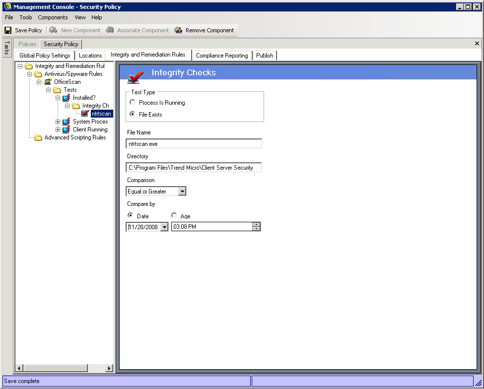
To create a new check, right-click Integrity Checks from the policy tree on the left, then click . Select one of the two check types and enter the information described below:
Process is Running
This check is used to determine if the software is running at the time of the triggering event (i.e., the AV client). The only information required for this check is the executable name.
File Exists
This check is used to determine if the software is current and up-to-date at the time of the triggering event.
Enter the following information in the provided fields:
-
File Name: Specify the filename that you want to check.
-
File Directory: Specify the directory where the file resides.
-
File Comparison: Select a date comparison from the drop-down list:
-
None
-
Equal
-
Equal or Greater
-
Equal or Less
-
-
Compare by: Specify or .
-
ensures that the file is no older than a specified date and time (for example, the date of the last update).
-
ensures that the file is no older than a specific time period, measured in days.
-
NOTE:The Equal file comparison is treated as Equal or Less when using the check.
The checks are run in the order entered.
Advanced Scripting Rules
ZENworks Endpoint Security Management includes an advanced rule scripting tool that gives administrators the ability to create extremely flexible and complex rules and remediation actions.
To access this control, click the tab, then click the icon in the policy tree on the left.
Figure 6-30 Advanced Scripting
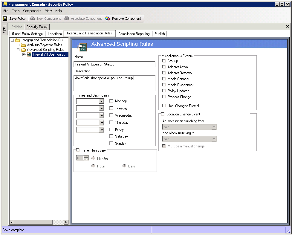
The scripting tool uses either of the common scripting languages, VBScript or JScript, to create rules that contain both a trigger (when to execute the rule) and the actual script (the logic of the rule). The administrator is not restricted on the type of script to be run.
Advanced scripting is implemented sequentially, along with other integrity rules. Therefore, a long-running script will prevent other rules (including timed rules) from executing until that script is complete.
To create a new advanced scripting rule:
-
Right-Click from the components tree, then click .
-
Name the rule and provide a description.
-
Specify the triggering event(s)
-
Times and Days to Run: Specify as many as five different times for the script to run. The script runs weekly, on the selected day(s).
-
Timer Run Every: Specify how often to run the timer.
-
Miscellaneous Events: Specify the events on the endpoint that trigger the script.
-
Location Change Event: Specify the location change event that triggers the script. These events are not independent; they are additive to the previous event.
-
Check Location Event: The script runs at all location changes.
-
Activate when switching from: The script runs only when the user leaves this (specified) location to any other location.
-
Activate when switching to: The script runs when the user enters this (specified) location from any other location (if was given a location parameter (example: office), the script runs only when the location switches from office to the specified location).
-
Must be a manual change: The script runs only when the user manually switches from or to a location.
-
-
-
Create any Script Variables. For more information see Script Variables.
-
Write the Script Text. For more information, see Script Text.
-
Click .
To associate an existing advanced scripting rule:
-
Select Advanced Scripting Rules in the components tree and click Associate New
-
Select the desired rule(s) from the list
-
The trigger event, variables, or script may be re-defined
NOTE:Changing the settings in a shared component will affect ALL OTHER instances of this same component. Use the Show Usage command to view all other policies associated with this component.
-
Click Save
Script Variables
This is an optional setting, which permits the Administrator to define a variable (var) for the script and either be able to use ZENworks Endpoint Security Management functionality (i.e., launch defined custom user messages or hyperlink; switch to a defined location or firewall setting) or have the freedom to change the value of a variable without changing the script itself.
Figure 6-31 Script Variables
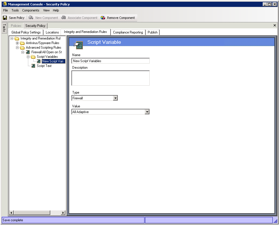
To create a new script variable:
-
Select Script Variables from the components tree and click Add New
-
Name the variable and provide a description
-
Select type of variable:
-
Custom User Messages - defines a custom user message which can launch as an action
-
Firewall - defines a firewall setting which can be applied as an action
-
Hyperlinks - defines a hyperlink which can be launched as an action
-
Location - defines a location which can be applied as an action
-
Number - defines a number value
-
String - defines a string value
-
-
Select/enter the value of the variable
-
Click Save. Repeat the above steps to create a new variable
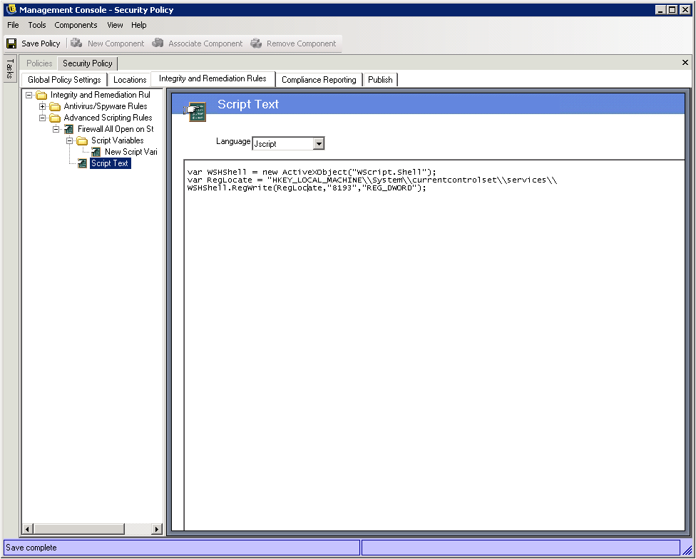
Script Text
The ZENworks Endpoint Security Management Administrator is not limited to the type of script the Endpoint Security Client may execute. It is recommended that ANY script be tested prior to distributing the policy.
Select the script type (Jscript or VBscript) and enter the script text in the provided field. The script may be copied from another source and pasted into the field. See Section 6.3.11, Rule Scripting Parameters, for acceptable script syntax.
Figure 6-32 Script Text Window
6.2.4 Compliance Reporting
Because of the level and access of the Endpoint Security Client's drivers, virtually every transaction the endpoint performs can be reported. The endpoint can have each optional system inventory run for troubleshooting and policy creation purposes. To access this control, open the Compliance Reporting tab.
NOTE:Reporting is not available when running the Stand-Alone Management Console
Figure 6-33 Compliance Reporting
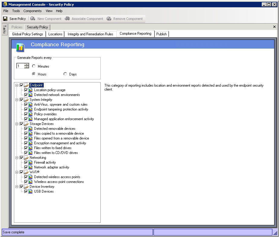
To run compliance reporting for this policy, perform the following steps:
-
Define the Send Time. This is the timeframe that data will be uploaded from the Endpoint Security Client to the Policy Distribution Service.
-
Check each report category, or type, you wish to capture.
The following reporting features are available:
Endpoint
-
Location policy usage - the Endpoint Security Client will report all location policies enforced and the duration of that enforcement
-
Detected network environments - the Endpoint Security Client will report all detected network environment settings
System Integrity
-
Anti-virus, spyware, and custom rules - the Endpoint Security Client will report the configured integrity messages based on test results
-
Endpoint tampering protection activity - the Endpoint Security Client will report any attempts to tamper with the security client
-
Policy overrides - the Endpoint Security Client will report all attempts to initiate the administrative override on the security client
-
Managed application enforcement activity - the Endpoint Security Client will report all enforcement activities for managed applications
Storage Devices
-
Detected removable devices - the Endpoint Security Client will report all removable storage devices detected by the security client
-
Files copied to a removable device - the Endpoint Security Client will report files that are copied to a removable storage device
-
Files opened from a removable device - the Endpoint Security Client will report files that are opened from a removable storage device
-
Encryption management and activity - the Endpoint Security Client will report encryption/decryption activity using SES
-
Files written to fixed drives - the Endpoint Security Client will report the number of files that have been written to the machine’s fixed drives
-
Files written to CD - the Endpoint Security Client will report the number of files that have been written to the machine’s CD and DVD drives
Networking
-
Firewall activity - the Endpoint Security Client will report all traffic blocked by the firewall configured for the applied location policy. Enabling this report may result in large volumes of data being gathered
WARNING:The following data can overwhelm a database very quickly when gathered. A test of ONE Endpoint Security Client reported 1,115 data uploads of blocked packets over a 20 hour period. It is recommended that a monitoring and tuning period with a test client in the affected environment be run prior to wide-scale deployment.
-
Network adapter activity - the Endpoint Security Client will report all traffic activity for a managed network device
Wi-Fi®
-
Detected wireless access points - the Endpoint Security Client will report all detected access points
-
Wireless access point connections - the Endpoint Security Client will report all access point connections made by the endpoint
Device Inventory
-
USB Devices - the Endpoint Security Client will report all USB devices
6.2.5 Publishing Security Policies
Completed security policies are sent to the end-users using the publishing mechanism. Once a policy has been published, it can be further updated with the end-user receiving updates at their scheduled check-ins. To publish a policy, click the Publish tab. The following information is displayed:
-
The current directory tree
-
The policy's created and modified dates
-
The Refresh and Publish buttons
Figure 6-34 Publish a Security Policy
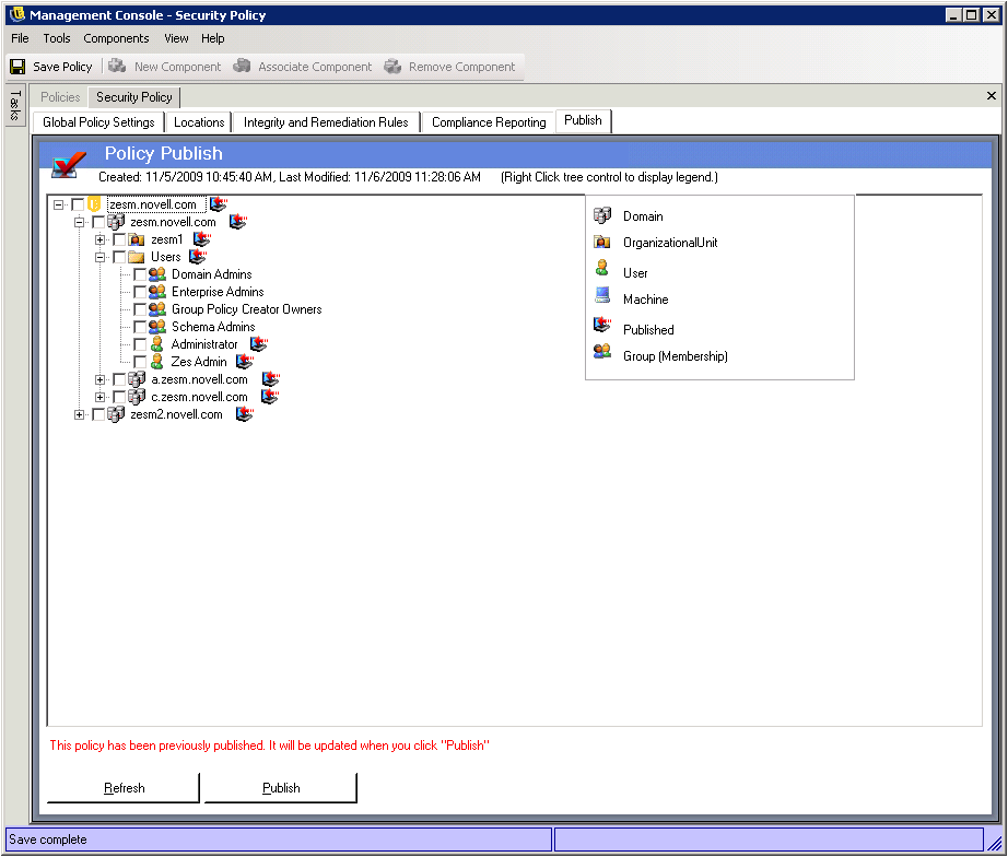
Based on the current user's publishing permissions, the directory tree may display with one or more of the selections in red. Users will NOT be permitted to publish to any users/groups displayed in red.
Users and their associated groups will not display until they have authenticated to the Management Service. Changes in the corporate directory service may not immediately display in the Management Console. Click Refresh to update the directory tree for the Management Service.
To publish a policy, perform the following steps:
-
Select a user or computer group (or single user or computer) from the directory tree.
-
Click Publish.
Updating a Published Policy
Once a policy has been published to the user(s) or computer(s), simple updates can be maintained by editing the components in a policy, and re-publishing. For example, if the ZENworks Endpoint Security Management Administrator needs to change the WEP key for an access point, the adminstrator only needs to edit the key, save the policy, and click Publish. The affected end-users and computers receive the updated policy (and the new key) at their next check-in.