DLCI Connections Creating a
Logical Partial Mesh
Typical WANs use less than 20 percent of the available bandwidth. However, because of the bursty nature of WAN traffic, they need the added capacity to handle bursts of traffic much greater than the average line utilization. This means that these expensive WAN circuits are idle approximately 80 percent of the time.
NetWare Link/Frame Relay helps save on connection access rates. Packet switching using NetWare Link/Frame Relay is bandwidth-efficient, allowing multiple virtual circuits to share one physical line. In addition, carriers allow oversubscription, which is the total bandwidth for all configured virtual circuits that might exceed the physical circuit bandwidth.
You can set up each virtual circuit with the frame relay service provider to support the bandwidth needed for that connection. With multiple virtual circuits, each sharing a percentage of the bandwidth, the aggregate line usage can approach 100 percent. Individual virtual circuits can also burst above the committed information rate; this capability is referred to as bandwidth-on-demand or dynamic allocation of bandwidth.
Frame relay service supports permanent virtual circuits (PVCs). PVCs require network administrative setup at subscription time. NetWare Link/Frame Relay (based on the ITU-T LAP-D or LAP-F protocol) provides bandwidth-on-demand and, by providing multiple virtual circuits per physical access port, reduces the connection access cost and customer investment in equipment.
This frame-switching protocol is optimized for modern reliable digital and fiber-optic transmission networks. It is a LAN-to-WAN interconnection technology for routers and bridges. In addition to containing high-bandwidth and low-delay characteristics, NetWare Link/Frame Relay is also an effective way to optimize bandwidth, consolidate networks, and do multiprotocol bridging and routing. You can multiplex multiple protocols over a Data Link Connection Identifier (DLCI), which identifies the preestablished path (the PVC) through the frame relay network to the correct destination. The DLCI constitutes the virtual circuit number.
Because of the high-speed requirement and the highly reliable transmission media, the NetWare Link/Frame Relay protocol design has very little protocol overhead. Only level 2, the Data-Link layer in the Open Systems Interconnection (OSI) model, is involved in the actual data transfer.
Because acknowledgment and retransmission requirements are eliminated, the internodal processing and its associated delay are minimized. NetWare Link/Frame Relay leaves it up to the higher-level protocols at the end-user devices to ensure reliable end-to-end data transfer. Because of this, NetWare Link/Frame Relay requires both reliable transmission media and higher-level protocols to operate efficiently and reliably.
The frame relay network does not correct or recover errors in frames or retransmit discarded frames. Frames can be discarded along the way because of transmission error, illegal frames, or network congestion. NetWare Link/Frame Relay assumes that the end point's higher-level protocols are responsible for end-to-end delivery. These devices operate with multiple-level protocols that can detect and recover from data loss in the connection.
Once the router is set up and initialized, it "listens" for an incoming call from the frame relay network to establish the connection. Whenever an end point needs to send data, it uses a DLCI (or virtual circuit number) to identify the preestablished path (the PVC) through the frame relay network to the correct destination.
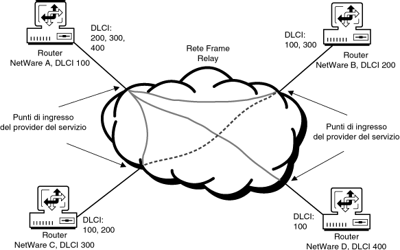
However, an end point cannot use PVCs dynamically to communicate with other end points on a network. DLCIs are assigned by the frame relay network provider at setup to define each destination. A logical mesh can also be formed with only one physical connection to the network. This is a cost savings feature for LAN interconnections. Figure 8-2 shows four routers connected in a logical partial mesh in a frame relay network.
Figure 8-2.
DLCI Connections Creating a
Logical Partial Mesh
Table 8-1 shows the actual connections available in Figure 8-2, based on the DLCIs assigned for each router's connection.
Router |
DLCIs |
Connections to Routers |
|---|---|---|
A |
200, 300, 400 |
B, C, D |
B |
100, 300 |
A, C |
C |
100, 200 |
A, B |
D |
100 |
A |