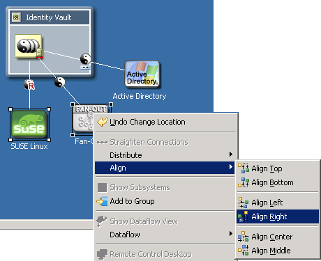
7.11 Aligning and Laying Out Components
Alignments place objects in the same horizontal or vertical plane. Alignments help you see relationships in your model. You can align or attach items to the left, center, or right of alignment guides.
When you move the guide, attached items move with it, staying attached in the same relative positions.
To align components:
-
Press Ctrl, then select more than one item.
-
Right-click, then select .
-
Select an alignment option.
You can also attach an item by dragging it to a guide. After you wait a moment, the guide line is highlighted, indicating that the item is attached.You can align within the same group but not across groups.
Guides that you set up are restored the next time that you run Designer. You don’t need to re-create them.
Also, the alignments and attachments (left, center, or right) are stored in the project on a per-item basis, so that they are also restored.
7.11.1 Alignment Hints
Horizontal and vertical “hint” lines automatically show as you drag items into vertical or horizontal alignment with neighboring items.
Figure 7-30 Alignment Hints
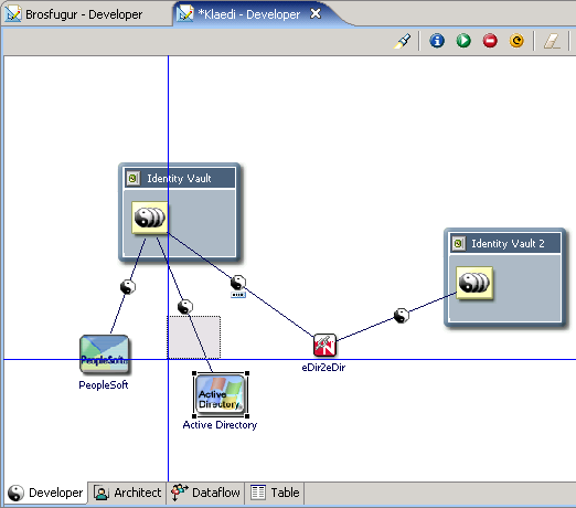
The Alignment Hints feature is off by default. To turn it on, click > .
Horizontal and vertical hint lines automatically show as you drag items into vertical or horizontal alignment with neighboring items.
7.11.2 Using Rulers
To turn on the horizontal and vertical rulers:
-
Click the Modeler space to make it active.
-
Click > .
To create a guide (line), click either ruler.
To anchor items to a guide, drag the items in the model to the line.
To simultaneously move all anchored items, drag the line.
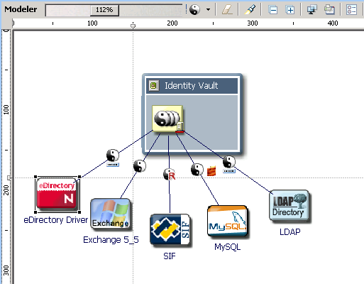
7.11.3 Using a Grid
Figure 7-31 The Modeler’s Grid
When the grid is on, the snap-to-grid functionality is on.
To turn grid lines on and off:
-
Click the Modeler, so that the Modeler is the active view.
-
Click > .
To coerce objects to not align with the grid, temporarily turn off snap-to-grid by holding down the Alt key. (Linux doesn’t support this functionality.)
To constrain items to north-south or east-west coordinates, press Shift while dragging the items.
To change the grid size:
-
Click > > > > .
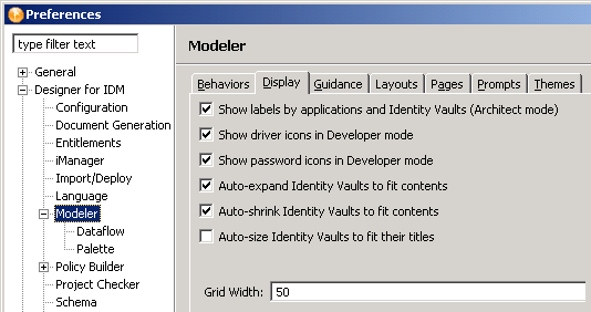
-
Type a value in the field.
7.11.4 Distributing Applications
Figure 7-32 Distributing Applications
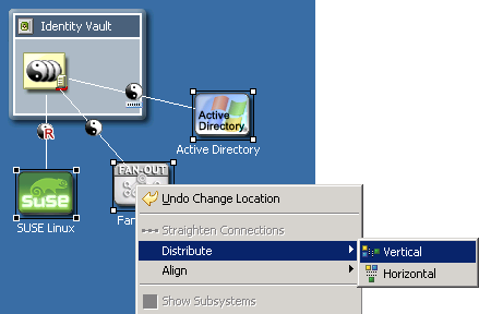
To equally distribute (space) applications horizontally or vertically:
-
Press Ctrl, then select three or more items.
-
Right-click, then select .
-
Select a distribution (for example, ).
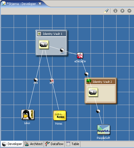
7.11.5 Auto-Layouts
Designer ships with a number of predefined layout topologies: circle, half-circle, star, box, and different fan-out layouts.
Figure 7-33 A Circle Layout
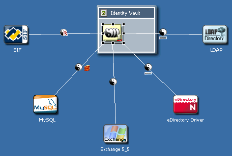
These layouts are set on a per-driver-set basis. Therefore, each driver set can have its own layout.
To select a layout:
-
Right-click a driver set, then select .
-
Select an arrangement (for example, ).
If your model has an incorrect layout, the layout options are dimmed.
After you set a layout, applications that you connect will automatically snap into that layout. Certain connected objects (for example, multi-driver connections, eDir-to-eDir connections, and applications that are connected but reside in a different Domain Group) are ignored. They aren’t included in the layout, and they don’t disturb it.
An option on the Arrange Applications submenu on the Modeler’s context menu enables you to expand or contract the layout arrangement. This option makes all spokes of the layout longer or shorter when you drag a slider.
7.11.6 Layouts to Use for Imports
To specify what layout to use on new driver sets that you import:
-
Select > > .
-
Click > .
-
Select an arrangement (for example, ), then click .