3.3 Selecting a Modeling Mode
The Modeler has tabs along the bottom, so that you can switch among different modeling modes. The modes have different advantages, depending on the task you’re trying to do and the role that you are acting in.
Figure 3-2 Modeler Modes

The modes are synchronized with each other with selection, data, and content. They are also synchronized with the Outline View and Thumbnail view.
As you switch modes in the Modeler editor, the editor tab at the top displays the mode that you are in. Also as you switch modes in the Modeler editor, Designer also remembers and restores to the Modeler page you were last on when you close and re-open a project. This helps you stay in the last mode you were last in.
By default, the theme preference is different for each mode. To configure each theme independently in the Modeler preferences:
-
Click > then select > .

-
Click the s tab.
-
Select a theme, then click .
3.3.1 Developer Mode
Figure 3-3 Developer Mode
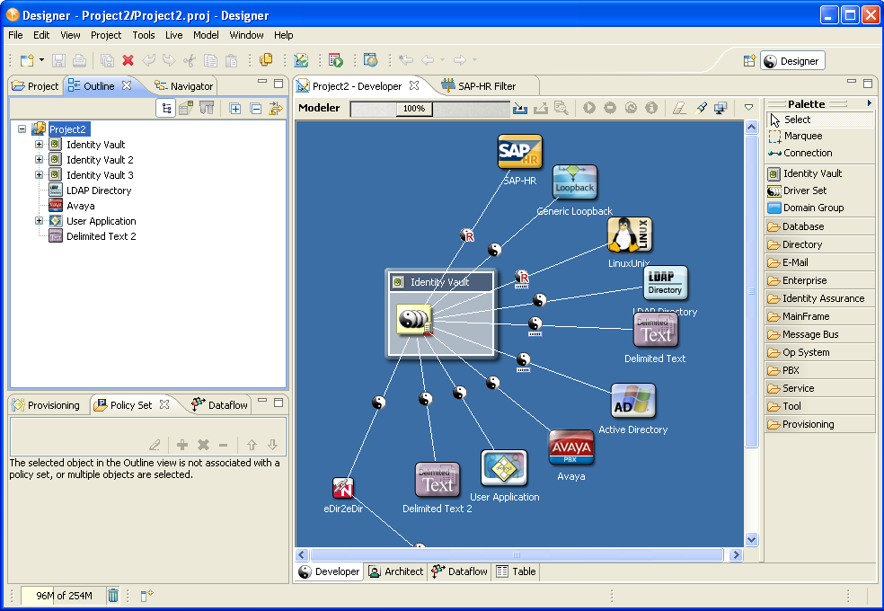
Use Developer mode to do all low-level operations with driver sets, drivers, policies, and applications. This mode lets you manage all of the visual elements and configuration details that you need to fully build and deploy an identity solution.
In Developer mode, the palette organizes the applications and systems into categories. You can customize them to show up as one alphabetical list by using the Modeler Preferences. See Palette Page.
Working with Labels
Figure 3-4 An Application’s Label

By default in both Developer and Architect modes, labels appear under application icons in the Modeler. They also appear above Identity Vaults in Architect mode.To configure these labels to not appear, use the Modeler Preferences. See Modeler.
3.3.2 Architect Mode
Figure 3-5 Architect Mode

Use the Architect mode to work at a design level for your projects. Because the design level doesn’t show drivers, driver sets, or policies, you focus more on systems. This mode helps you do large-scale design, which is more intuitive to architects and business strategists.
It is quite likely that you will start in this mode when you begin each project. You will probably spend time putting together an accurate diagram of your enterprise as you consult with various people throughout your organization. As you do so, you should capture key information on each system, such as the owner, contact information, machine environment, software versions, and authentication credentials. As you go through this process, you will also define your project requirements, start thinking about your data, and capture that information in your project.
When the time is right, you can switch to the Developer mode and delve into the technical details of building a working solution. Depending on the size of your project and the makeup of your team, you could have architects and designers build high-level solutions with Designer in the Architect mode, and then send the project to identity developers who understand the details of writing policies and configuring systems. They can share the same project.
In Architect mode, you can connect any design element with any other design element, application, image, or Identity Vault. The connecting lines enable you to express any relationship, making Architect mode a general-purpose, high-level business modeler. The Architect-mode lines don’t display when you switch to the Developer mode.
NOTE:When you add icons representing driver applications through the Architect mode, you will need to configure those drivers in the Developer mode. Once you have added the necessary drivers and switch to the Developer tab, right-click the line between the driver icon and the driver set, then select .
The design elements have connectivity information tied to them. You can use design elements to perform live operations or to remotely control other elements that are in your environment but are not necessarily included in your Identity Manager infrastructure.
When using the Architect mode, you should be familiar with the following:
The Palette in Architect Mode
In Architect mode, the palette lists all applications in one folder and design elements in another folder. The Architect Modeler view now contains all of the graphical modeling tools that are present in the Developer Modeler view. This includes:
-
Rulers
-
Snap-in guides
-
Alignment hints
-
Grid
-
Snap-in movement
The Graphics folder has an Image icon. When you drag this icon to the Modeler, Designer displays a generic graphic:
Figure 3-6 The Image Icon
To edit the properties of this icon:
-
Right-click the icon, then select .

-
In the field, replace with a caption.
-
Browse to and select a replacement graphic, then click .
You might need to reduce the size of the graphic before importing it.
After the image is in the Modeler, you can drag it, change it, connect lines to it, align or distribute it, or delete it.
High-Level Data Flows in Architect Mode
To set data flows in Architect mode:
-
Right-click the line between an application and an Identity Vault.
-
Select .
-
Right-click the line again and select.
-
Specify synchronization and notification events, then click .
This option is used the same way as in Developer mode except that in Architect mode, Designer automatically configures all the details (schema, filters, and mapping policies) for you. You won’t see the Data Flow Wizard for these details. Before deployment, you can edit the details by using Developer mode.
Tasks
You can perform the following tasks in Architect mode:
-
Straighten connections (edges). See Section 3.11, Aligning and Laying Out Components.
-
View Password Sync icons and edit synchronization. See Section 7.6, Integrating Passwords.
-
Auto-connect eDir-to-eDir.
-
When deleting the driver line, view a prompt to confirm drivers being deleted.
-
Display design elements in your model.
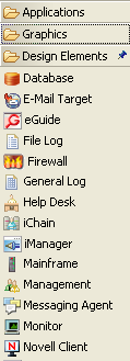
Open the folder on the palette, drag design elements onto the Modeler, and connect the design elements.
Figure 3-7 Items in the Design Elements Folder
3.3.3 Dataflow Mode
Figure 3-8 Dataflow Mode
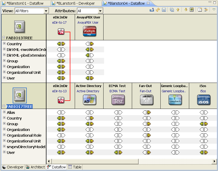
The Dataflow mode launches the Dataflow Editor, so that you can see all of the filters that control how data flows between the connected systems and Identity Vaults. In the Dataflow Editor, you can right-click an eDir-to-eDir connection and have the option to remove the connection.
The Dataflow mode is synchronized with the Modeler and with the Outline view when you add, delete, change, or synchronize objects. Also, you can see how passwords flow from each server. See Section 7.0, Managing the Flow of Data.
The Dataflow toolbar enables you to perform the following actions:
-
Deploy driver filters for all drivers in the Dataflow view
-
Refresh the Dataflow view’s UI screen
-
Save the current Dataflow view to an HTML file. You can select a directory to put the file.
-
Save all of the filtered views (Notify, Sync, Reset, Password Sync) to an HTML files. You can select a directory to put the files.
-
Go up and down to the Identity Vaults
-
Create a new Identity Vault
-
Add an application driver for a connected system
-
Filter Identity Vaults and application drivers out of the Dataflow view
The pull-down menu allows you to perform the following:
-
Expand all containers
-
Collapes all containers
-
Launch Dataflow preferences
-
Get help
The Architect and Modeler views contain the same pull-down menu with the same functionality.
3.3.4 Table Mode
Figure 3-9 Global Table Editor
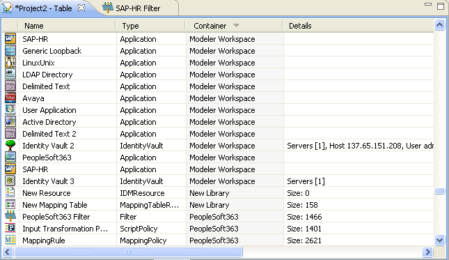
Table mode provides a Global Table editor, which lists all design elements in the project. You can scroll this table to quickly scan essential information, such as the element’s type, the container where the element resides, and details, such as an element’s size, or driver and serverinformation. You can efficiently find all items of a particular type and edit their settings.
To edit an entry in the table, double-click a line, or right-click a line and select either , then an editor. You can also right-click a line, select , and Designer launches the editor that has been associated with the action. For example, drivers open their Properties page, policies open in the Policy Builder, etc.
When you select an entry in the table, Designer synchronizes the selection with the Outline view, so that you can view the selection’s container.
To sort the lists, click a column header.