10.5 Legacy Filter Configuration
-
Log in to iManager, then select .
-
From the list, select the server where the filters are to be configured by clicking the icon, then click .
To set up the Packet Filtering Configuration Task, refer to Section 10.5.1, Configuring the Packet Forwarding Filter.
To ensure that the configured filters are active, check to see that you have enabled filter support using INETCFG.
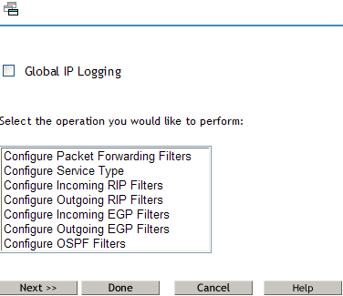
Select any one of the following for configuration:
-
Configuring Packet Forwarding Filter: TCP/IP Packet Forwarding Filters allow the router to selectively filter packets based on their packet type, source, and destination.
-
Configuring Service Type: Service Type includes the System and User defined packet types used for configuring Packet Forwarding filters.
-
Routing Information Protocol (RIP) Filter: RIP filters are used to control the propagation of routing information by this router. They provide a low level of security by hiding the existence of specific IP networks from other routers. There are two types of routing filters, incoming and outgoing.
Incoming RIP filters restrict the acceptance of routing information from the adjacent routers.
Outgoing RIP filters restrict the routing information advertised by the router to its adjacent routers.
-
EGP Filter: The routes that the router can share with the EGP peers are defined with EGP filters. There are two types of EGP filters: Incoming and Outgoing.
Incoming EGP filters restrict what routes can be accepted from an EGP peer.
Outgoing EGP filters restrict what routes learned from RIP, OSPF, or static routes can be propagated to EGP peers.
-
Configuring OSPF Filter: The router can use OSPF to exchange routing information within its Autonomous System. OSPF External Route Filters define the route and the source of the source of the route that will be propagated into the OSPF domain.
-
-
Select an operation from the list and click to continue.
-
Select the Global IP Logging check box if you want to enable global IP logging. The global logging status for all filter types can be enabled or disabled from the configuration menu.
-
Click if you want to save changes to IP logging and exit Filter Configuration.
-
Click Cancel to exit Filter Configuration.
The following sections contain information about configuring filter types:
10.5.1 Configuring the Packet Forwarding Filter
-
Log in to iManager, then select .
-
From the list, select the server where the filters are to be configured by clicking the icon, then click .
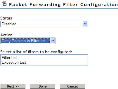
This page helps you to set the properties of the selected filter type:
Status: Choose between Disabling or Enabling the selected filters. If Filtering Support has been enabled in inetcfg.nlm for this protocol, altering the status will cause configured filters to immediately become active (Enabled) or inactive (Disabled).
Action: Choose between Denying and Permitting packets on the filter list. Specify the action taken when a packet matches a filter in the Filter List. If the filters in the Exception List overlap with the filters in the Filters List, the Exception List is used.
Select the list of Filters to be Configured: Select the list of filters to be configured; choose between the Filter List or the Exception List.
Filter List: Displays all configured filters. You can add new filters, or delete or modify existing filters. The data packets that match any filter are either permitted or denied depending on the setting of the Action parameter. Data packets that match any filter in the Exceptions List are not filtered, even if they match a filter in the Filters List.
Exception List: Displays the exceptions to the filters defined in the Filters List, and allows you to specify additional exceptions. Exception filters take priority over filters in the Filter List. If a packet does not match an exception filter, it is checked against the Filters List. The packet is filtered if it matches any filter.
-
Select or and click to configure filters in that list. The Packet Forwarding Filter Configuration page is displayed.
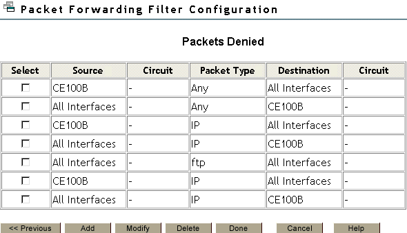
This page gives you a summary of packet forwarding filters.
You can add new filters, or delete or modify existing filters. The data packets that match any filter are either permitted or denied depending on the setting of the Action parameter. Data packets that match any filter in the Exceptions List are not filtered, even if they match a filter in the Filters List.
-
To change properties for the filters, select the filter that you want to modify and click .
-
Click to add a new filter.
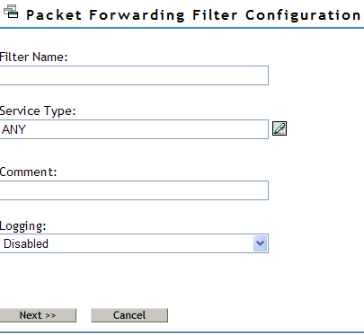
This page helps you to add or modify your filter properties.
Filter Name: Specify the name of the packet filter. This is the name of the filter object that would be created in Novell eDirectory.
Service Type: Specify the service type to be filtered. Click the button to view a list of defined TCP/IP service types. You can select an entry for the filter being edited. If you want to add or modify or delete user-defined service types, go to the Configure Service Type option on the configuration menu.
Comment: Specify a short comment in this field, to save in the database along with the other entries in the form.is
Logging: Choose to enable or disable this option.
-
Enable: The header of the packet that matches the options in the filters or exceptions are logged as long as the global logging status and the filters/exception logging status are enabled. The Log file is a Btrieve database file (csaudit.log) located at sys:\etc\logs\ippktlog directory.
-
Disable: Packets that match the options in filters or exceptions are not logged. Data logging slows down the server’s performance and you should turn it on for a short time only. The local logging status can be enabled or disabled from the filter/exception definition menu.
Specify a name in the Name dialog box, then click .
-
-
You can add or modify the following filter properties.
Name: Gives you the name of the packet filter. This is the name of the filter object that would be created in Novell eDirectory.
Service Type: Defines the service type to be filtered. Click the button to view a list of defined TCP/IP service types. You can select an entry for the filter being edited. If you want to add or modify or delete user-defined service types, go to the Configure Service Type option on the configuration menu.
Comment: Specify a short comment in this field, to save in the database along with the other entries in the form.is
Logging: Choose to enable or disable this option.
-
Enable: The header of the packet that matches the options in the filters or exceptions are logged as long as the global logging status and the filters/exception logging status are enabled. The Log file is a Btrieve database file (csaudit.log) located at sys:\etc\logs\ippktlog directory.
-
Disable: Packets that match the options in filters or exceptions are not logged. Data logging slows down the server’s performance and you should turn it on for a short time only. The local logging status can be enabled or disabled from the filter/exception definition menu.
-
-
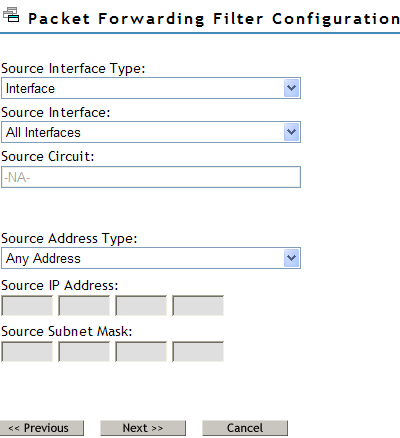
Click to add or alter the source information for the filter.
-
You can to add or modify the following source information for the filter:
Source Interface Type: Select the source interface type of the TCP/IP packet forwarding filter. The available source types are Interface and Interface Group.
Source Interface: Select a source interface.
Source Circuit: Specify the information about the circuit to be configured. The source circuit is valid only if the source interface is of WAN media type. The default source circuit value is All Circuits.
Source Address Type: Select the Source Address Type of the TCP/IP packet forwarding filter. The available source types are Network, Host, or Any Address.
Source IP Address: Gives the IP address of your network or host.
Source Subnet Mask: Gives the subnetwork mask of your network.
-
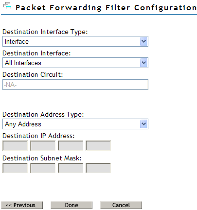
Click to configure the destination information for filters.
-
You can add or modify the following destination information for the filter:
Destination Interface Type: Select the destination interface type of the TCP/IP packet forwarding filter. The available source types are Interface and Interface Group.
Destination Interface: Select the destination interface.
Destination Circuit: Specify the information about the circuit to be configured. The destination circuit is valid only if the destination interface is of WAN media type. The default destination circuit value is All Circuits.
Destination Address Type: Select the Destination Address Type of the TCP/IP packet forwarding filter. The available types are Network, Host, Multicast, or Any Address.
Destination IP Address: Gives the Network, Host or Multicast address.
Destination Subnetwork Mask: Gives the subnetwork mask of your network.
-
Cick to save changes to the status or action of this filter type and return to the filter configuration menu.
-
Click to discard changes to the status or action and return to the filter configuration menu.
10.5.2 Configuring the Service Type
This page allows you to configure new TCP/IP service types and modify the property of existing ones.
-
Log in to iManager, then select .
-
From the list, select the server where the filters are to be configured by clicking the icon, then click .
-
Select , then click
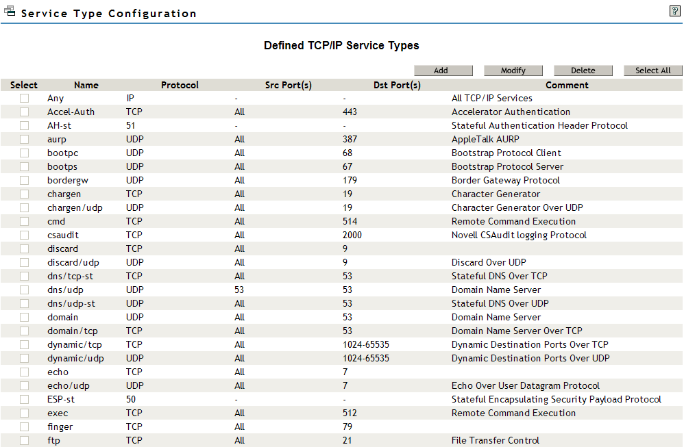
This page gives you a summary of defined TCP/IP service types.
-
You can add new service types, or delete or modify only User Service types.
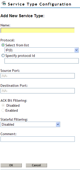
Fill in the following fields:
Name: Name of the TCP/IP service type.
Protocol: Either select from a list of commonly used internet protocols or specify a valid protocol ID between 0 - 255.
Source Port: Define a single TCP/IP port or range of ports separated by a hyphen for the TCP or UDP protocols. Valid port numbers range from 1 to 65535. If not defined, the default value for this field is All.
Destination Port: Define a single TCP/IP port or range of ports separated by a hyphen for the TCP or UDP protocols. Valid port numbers range from 1 to 65535. If not defined, the default value for this field is All.
ACK Bit Filtering: This field is enabled only if the protocol selected is TCP. If the TCP ACK Bit filtering is enabled in a filter route, only the packets with the ACK Bit set are allowed through. This will effectively block all the connections being initiated, in the direction defined by the filter rule. TCP ACK Bit filtering is often applied to all inbound TCP packets in a network.
Stateful Filtering: If stateful filtering is enabled in a filter rule, a dynamic filter is also created in the reverse of the direction that is defined by the filter rule. The reverse filter is created with the information such as source IP address, source interface, source port, destination IP address, destination interface, and destination port. This information is stored in a table that will later be used to compare against the reply. If it is not a reply to the original request packet, stateful filtering will not allow the packet through.
Stateful filtering supports both connection and connectionless protocols. For ICMP packets, only the reply ICMP messages are allowed. ICMP redirect messages will not be allowed. Stateful filtering is slower than the current static filtering but it is more secure. It does not open up all the ports as static filters do; instead, dynamic filters are created with more specific information on the IP address, source, and destination ports.
Comment: Specify a short comment in this field to save in the database along with the other entries in the form.
-
Click to add the Service Type.
10.5.3 Configuring an Incoming RIP Filter
You can configure the incoming RIP filters as follows:
-
Log in to iManager, then select .
-
From the list, select the server where the filters are to be configured by clicking the icon, then click .
-
Select , then click
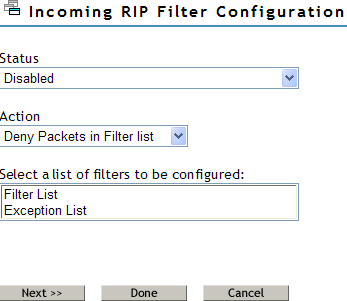
This page helps you to set the properties of the selected filter type.
Status: You can either enable or disable the selected filters. If Filtering Support has been enabled in inetcfg.nlm for this protocol, altering the status causes configured filters to immediately become active (Enabled) or inactive (Disabled).
Action: You can either deny or permit packets on the filter list. Specify the action taken when a packet matches a filter in the Filter List. If the filters in the Exception List overlap with the filters in the Filters List, the Exception List is used.
Select the List of Filters to Be Configured: You can select the list of filters to be configured. Choose between the Filter List or the Exception List.
-
Filter List: Displays all configured filters. You can add new filters, or delete or modify existing filters. The data packets that match any filter are either permitted or denied depending on the setting of the Action parameter. Data packets that match any filter in the Exceptions List are not filtered, even if they match a filter in the Filters List.
-
Exception List: Displays the exceptions to the filters defined in the Filters List, and allows you to specify additional exceptions. Exception filters take priority over filters in the Filter List. If a packet does not match an exception filter, it is checked against the Filters List. The packet is filtered if it matches any filter.
-
-
Select Filter List or Exception List and click to configure filters in that list. The next page displays the list of routes denied or always permitted depending on whether you have selected the Filter List or Exception list respectively.
If the Action is deny, then the RIP routes that match the criteria of a filter in the Filter List are not accepted by the router. All other RIP routes are not accepted. If the Action is Permit, then the RIP routes that match the criteria of a filter in the Exception List are always accepted by the router, even if another filter in the Filter List is configured to do the opposite.
-
Click Add to add new filters or select the filter you want to modify and click modify.
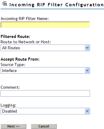
Fill in the following fields:
Incoming RIP Filter Name: Specify the name of the RIP filter. This name becomes the distinguished name of the filter in the eDirectory.
Route to Network or Host: Specify the host, route, or network to be filtered.
Source Type: Specify the source type that the router will accept or block the route to. Select from the list. The available types are Host, Interface, Interface Group, and Network.
Comment: Specify a short comment in this field to save in the database along with the other entries in the form.
Logging: Choose to enable or disable this option.
-
Enabled: the header of the packet that matches the options in the filters or exceptions is logged as long as the global logging status and the filters/exception logging status are enabled. The Log file is a Btrieve database file (csaudit.log) located at sys:\etc\logs\ippktlog directory.
-
Disabled: Any packet that matches the options in filters or exceptions is not logged. Data logging slows down the server’s performance and you should turn it on for a short time only. The local logging status can be enabled or disabled from the filter/exception definition menu.
-
-
Click to configure the filter information:
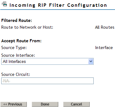
Fill in the following information:
Filtered Route: This section has the following fields:
-
Route to Network/Host: Specify a four-byte IP address in dotted decimal notation. For example: 130.57.172.0.
NOTE:When configuring RIP filters for IP networks you should be aware of the fact that depending on the network topology, RIP broadcasts on a particular interface might only advertise the networks even if the network has been divided into several subnetworks. Configuring a filter for a subnetwork of a network, in this case, will not stop information about the network itself from being included in the RIP broadcast. This means that you might need to configure a filter for the network and not the subnetwork to prevent the subnetwork information from being advertised on an interface. You can configure filters for subnetworks to prevent those subnetworks being advertised on other subnetworks of the same network, but be aware that their effectiveness will be influenced by the routing topology.
-
Subnetwork Mask: Specify a four-byte mask in dotted decimal format. 255.255.255.255 is invalid. The mask must also cover the nature mask.
Address Type of Routing Peer: This section has the following fields:
-
Source Type: Specifies whether the source is a Host, Interface, Interface Group, or Network.
-
Source Interface: If your Source Type is Interface or Interface Group, select a source location from the list of network interfaces.
-
Source Circuit: If the current source is of type Interface or Interface Group and is of WAN Media Type, specify the destination circuit parameters.
-
IP Address of Network: If your Source Type is Network or Host, specify the IP address.
-
Subnetwork Mask: If your Source Type is Network, specify the subnetwork mask.
-
-
Click to save changes to Status and/or Action of this filter type and return to the filter configuration menu.
After you save the changes, TCP/IP dynamically updates to the new configuration. The action taken on routes matching filters in this list is described in the Action field. You can select the Route and Source parameters from the list of defined values.
-
Click to discard changes to Status and/or Action and return to the filter configuration menu.
10.5.4 Configuring an Outgoing RIP Filter
You can configure the outgoing RIP filters as follows:
-
Log in to iManager, then select .
-
From the list, select the server where the filters are to be configured by clicking the icon, then click .
-
Select , then click
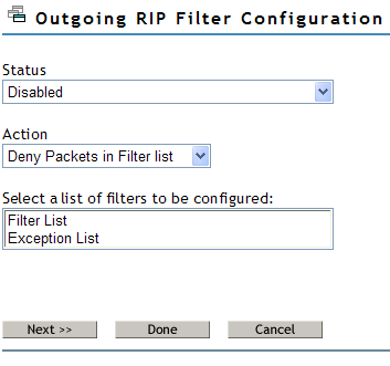
This page helps you to set the properties of the selected filter type.
Status: You can either enable or disable the selected filters. If Filtering Support has been enabled in inetcfg.nlm for this protocol, altering the status causes configured filters to immediately become active (Enabled) or inactive (Disabled).
Action: You can either deny or permit packets on the filter list. Specify the action taken when a packet matches a filter in the Filter List. If the filters in the Exception List overlap with the filters in the Filters List, the Exception List is used.
Select the List of Filters to Be Configured: You can select the list of filters to be configured. Choose between the Filter List or the Exception List.
-
Filter List: Displays all configured filters. You can add new filters, or delete or modify existing filters. The data packets that match any filter are either permitted or denied depending on the setting of the Action parameter. Data packets that match any filter in the Exceptions List are not filtered, even if they match a filter in the Filters List.
-
Exception List: Displays the exceptions to the filters defined in the Filters List, and allows you to specify additional exceptions. Exception filters take priority over filters in the Filter List. If a packet does not match an exception filter, it is checked against the Filters List. The packet is filtered if it matches any filter.
-
-
Select Filter List or Exception List and click to configure filters in that list. The next page displays the list of routes denied or always permitted depending on whether you have selected the Filter List or Exception list respectively.
If the Action is deny, then the RIP routes that match the criteria of a filter in the Filter List are not accepted by the router. All other RIP routes are not accepted. If the Action is Permit, then the RIP routes that match the criteria of a filter in the Exception List are always accepted by the router, even if another filter in the Filter List is configured to do the opposite.
-
Click Add to add new filters or select the filter you want to modify and click modify.
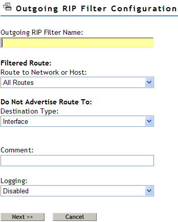
Fill in the following fields:
Outgoing RIP Filter Name: Specify the name of the RIP filter. This name becomes the distinguished name of the filter in the eDirectory.
Route to Network or Host: Specify the host, route, or network to be filtered.
Destination Type: Specify the destiantion type that the router will accept or block the route to. Select from the list. The available types are Host, Interface, Interface Group, and Network.
Comment: Specify a short comment in this field to save in the database along with the other entries in the form.
Logging: Choose to enable or disable this option.
-
Enabled: the header of the packet that matches the options in the filters or exceptions is logged as long as the global logging status and the filters/exception logging status are enabled. The Log file is a Btrieve database file (csaudit.log) located at sys:\etc\logs\ippktlog directory.
-
Disabled: Any packet that matches the options in filters or exceptions is not logged. Data logging slows down the server’s performance and you should turn it on for a short time only. The local logging status can be enabled or disabled from the filter/exception definition menu.
-
-
Click to configure the filter information:
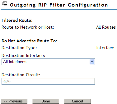
Fill in the following information:
Filtered Route: This section has the following fields:
-
Route to Network/Host: Specify a four-byte IP address in dotted decimal notation. For example: 130.57.172.0.
NOTE:When configuring RIP filters for IP networks you should be aware of the fact that depending on the network topology, RIP broadcasts on a particular interface might only advertise the networks even if the network has been divided into several subnetworks. Configuring a filter for a subnetwork of a network, in this case, will not stop information about the network itself from being included in the RIP broadcast. This means that you might need to configure a filter for the network and not the subnetwork to prevent the subnetwork information from being advertised on an interface. You can configure filters for subnetworks to prevent those subnetworks being advertised on other subnetworks of the same network, but be aware that their effectiveness will be influenced by the routing topology.
-
Subnetwork Mask: Specify a four-byte mask in dotted decimal format. 255.255.255.255 is invalid. The mask must also cover the nature mask.
Do Not Advertise Route To: This section has the following fields:
-
Destination Type: Specifies whether the destination is a Host, Interface, Interface Group, or Network.
-
Destination Interface: If your Source Type is Interface or Interface Group, select a source location from the list of network interfaces.
-
Destination Circuit: If the current source is of type Interface or Interface Group and is of WAN Media Type, specify the destination circuit parameters.
-
IP Address of Network: If your destination Type is Network or Host, specify the IP address.
-
Subnetwork Mask: If your destinationType is Network, specify the subnetwork mask.
-
-
Click to save changes to Status and/or Action of this filter type and return to the filter configuration menu.
After you save the changes, TCP/IP dynamically updates to the new configuration. The action taken on routes matching filters in this list is described in the Action field. You can select the Route and Source parameters from the list of defined values.
-
Click to discard changes to Status and/or Action and return to the filter configuration menu.
10.5.5 Configuring an Incoming EGP Filter
You can configure configure incoming RIP filters as follows:
-
Log in to iManager, then select .
-
From the list, select the server where the filters are to be configured by clicking the icon, then click .
-
Select , then click
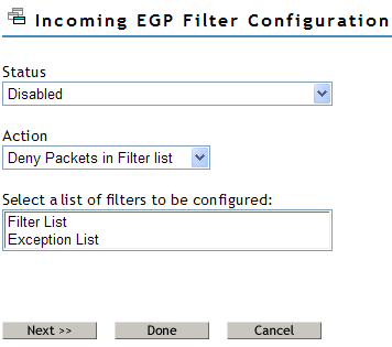
This page helps you to set the properties of the selected filter type.
Status: You can either enable or disable the selected filters. If Filtering Support has been enabled in inetcfg.nlm for this protocol, altering the status causes configured filters to immediately become active (Enabled) or inactive (Disabled).
Action: You can either deny or permit packets on the filter list. Specify the action taken when a packet matches a filter in the Filter List. If the filters in the Exception List overlap with the filters in the Filters List, the Exception List is used.
Select the List of Filters to Be Configured: You can select the list of filters to be configured. Choose between the Filter List or the Exception List.
-
Filter List: Displays all configured filters. You can add new filters, or delete or modify existing filters. The data packets that match any filter are either permitted or denied depending on the setting of the Action parameter. Data packets that match any filter in the Exceptions List are not filtered, even if they match a filter in the Filters List.
-
Exception List: Displays the exceptions to the filters defined in the Filters List, and allows you to specify additional exceptions. Exception filters take priority over filters in the Filter List. If a packet does not match an exception filter, it is checked against the Filters List. The packet is filtered if it matches any filter.
-
-
Select Filter List or Exception List and click to configure filters in that list. The next page displays the list of routes denied or always permitted depending on whether you have selected the Filter List or Exception list respectively.
If the Action is deny, then the EGP routes that match the criteria of a filter in the Filter List are not accepted by the router. All other EGP routes are not accepted. If the Action is Permit, then the RIP routes that match the criteria of a filter in the Exception List are always accepted by the router, even if another filter in the Filter List is configured to do the opposite.
-
Click Add to add new filters or select the filter you want to modify and click modify.
Fill in the following fields:
Incoming EGP Filter Name: Specify the name of the EGP filter. This name becomes the distinguished name of the filter in the eDirectory.
Route to Network or Host: Specify the host, route, or network to be filtered.
Source Type: Specify the source type that the router will accept or block the route to. Select from the list. The available types are Host, Interface, Interface Group, and Network.
Comment: Specify a short comment in this field to save in the database along with the other entries in the form.
Logging: Choose to enable or disable this option.
-
Enabled: the header of the packet that matches the options in the filters or exceptions is logged as long as the global logging status and the filters/exception logging status are enabled. The Log file is a Btrieve database file (csaudit.log) located at sys:\etc\logs\ippktlog directory.
-
Disabled: Any packet that matches the options in filters or exceptions is not logged. Data logging slows down the server’s performance and you should turn it on for a short time only. The local logging status can be enabled or disabled from the filter/exception definition menu.
-
-
Click to configure the filter information:
Fill in the following information:
Filtered Route: This section has the following fields:
-
Route to Network/Host: Specify a four-byte IP address in dotted decimal notation. For example: 130.57.172.0.
NOTE:When configuring RIP filters for IP networks you should be aware of the fact that depending on the network topology, RIP broadcasts on a particular interface might only advertise the networks even if the network has been divided into several subnetworks. Configuring a filter for a subnetwork of a network, in this case, will not stop information about the network itself from being included in the RIP broadcast. This means that you might need to configure a filter for the network and not the subnetwork to prevent the subnetwork information from being advertised on an interface. You can configure filters for subnetworks to prevent those subnetworks being advertised on other subnetworks of the same network, but be aware that their effectiveness will be influenced by the routing topology.
-
Subnetwork Mask: Specify a four-byte mask in dotted decimal format. 255.255.255.255 is invalid. The mask must also cover the nature mask.
Address Type of Routing Peer: This section has the following fields:
-
Source Type: Specifies whether the source is a Host, Interface, Interface Group, or Network.
-
Source Interface: If your Source Type is Interface or Interface Group, select a source location from the list of network interfaces.
-
Source Circuit: If the current source is of type Interface or Interface Group and is of WAN Media Type, specify the destination circuit parameters.
-
IP Address of Network: If your Source Type is Network or Host, specify the IP address.
-
Subnetwork Mask: If your Source Type is Network, specify the subnetwork mask.
-
-
Click to save changes to Status and/or Action of this filter type and return to the filter configuration menu.
After you save the changes, TCP/IP dynamically updates to the new configuration. The action taken on routes matching filters in this list is described in the Action field. You can select the Route and Source parameters from the list of defined values.
-
Click to discard changes to Status and/or Action and return to the filter configuration menu.
10.5.6 Configuring an Outgoing EGP Filter
You can configure configure incoming RIP filters as follows:
-
Log in to iManager, then select .
-
From the list, select the server where the filters are to be configured by clicking the icon, then click .
-
Select , then click
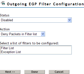
This page helps you to set the properties of the selected filter type.
Status: You can either enable or disable the selected filters. If Filtering Support has been enabled in inetcfg.nlm for this protocol, altering the status causes configured filters to immediately become active (Enabled) or inactive (Disabled).
Action: You can either deny or permit packets on the filter list. Specify the action taken when a packet matches a filter in the Filter List. If the filters in the Exception List overlap with the filters in the Filters List, the Exception List is used.
Select the List of Filters to Be Configured: You can select the list of filters to be configured. Choose between the Filter List or the Exception List.
-
Filter List: Displays all configured filters. You can add new filters, or delete or modify existing filters. The data packets that match any filter are either permitted or denied depending on the setting of the Action parameter. Data packets that match any filter in the Exceptions List are not filtered, even if they match a filter in the Filters List.
-
Exception List: Displays the exceptions to the filters defined in the Filters List, and allows you to specify additional exceptions. Exception filters take priority over filters in the Filter List. If a packet does not match an exception filter, it is checked against the Filters List. The packet is filtered if it matches any filter.
-
-
Select Filter List or Exception List and click to configure filters in that list. The next page displays the list of routes denied or always permitted depending on whether you have selected the Filter List or Exception list respectively.
If the Action is deny, then the EGP routes that match the criteria of a filter in the Filter List are not accepted by the router. All other EGP routes are not accepted. If the Action is Permit, then the RIP routes that match the criteria of a filter in the Exception List are always accepted by the router, even if another filter in the Filter List is configured to do the opposite.
-
Click Add to add new filters or select the filter you want to modify and click modify.

Fill in the following fields:
Outgoing EGP Filter Name: Specify the name of the EGP filter. This name becomes the distinguished name of the filter in the eDirectory.
Route to Network or Host: Specify the host, route, or network to be filtered.
Destination Type: Specify the source type that the router will accept or block the route to. Select from the list. The available types are Host, Interface, Interface Group, and Network.
Comment: Specify a short comment in this field to save in the database along with the other entries in the form.
Logging: Choose to enable or disable this option.
-
Enabled: the header of the packet that matches the options in the filters or exceptions is logged as long as the global logging status and the filters/exception logging status are enabled. The Log file is a Btrieve database file (csaudit.log) located at sys:\etc\logs\ippktlog directory.
-
Disabled: Any packet that matches the options in filters or exceptions is not logged. Data logging slows down the server’s performance and you should turn it on for a short time only. The local logging status can be enabled or disabled from the filter/exception definition menu.
-
-
Click to configure the filter information:
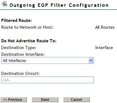
Fill in the following information:
Filtered Route: This section has the following fields:
-
Route to Network/Host: Specify a four-byte IP address in dotted decimal notation. For example: 130.57.172.0.
NOTE:When configuring EGP filters for IP networks you should be aware of the fact that depending on the network topology, EGP broadcasts on a particular interface might only advertise the networks even if the network has been divided into several subnetworks. Configuring a filter for a subnetwork of a network, in this case, will not stop information about the network itself from being included in the EGP broadcast. This means that you might need to configure a filter for the network and not the subnetwork to prevent the subnetwork information from being advertised on an interface. You can configure filters for subnetworks to prevent those subnetworks being advertised on other subnetworks of the same network, but be aware that their effectiveness will be influenced by the routing topology.
-
Subnetwork Mask: Specify a four-byte mask in dotted decimal format. 255.255.255.255 is invalid. The mask must also cover the nature mask.
Address Type of Routing Peer: This section has the following fields:
-
Destination Type: Specifies whether the destination is a Host, Interface, Interface Group, or Network.
-
Destination Interface: If your Destination Type is Interface or Interface Group, select a source location from the list of network interfaces.
-
Destination Circuit: If the current source is of type Interface or Interface Group and is of WAN Media Type, specify the destination circuit parameters.
-
IP Address of Network: If your Destination Type is Network or Host, specify the IP address.
-
Subnetwork Mask: If your Destination Type is Network, specify the subnetwork mask.
-
-
Click to save changes to Status and/or Action of this filter type and return to the filter configuration menu.
After you save the changes, TCP/IP dynamically updates to the new configuration. The action taken on routes matching filters in this list is described in the Action field. You can select the Route and Source parameters from the list of defined values.
-
Click to discard changes to Status and/or Action and return to the filter configuration menu.
10.5.7 Configuring an OSPF Filter
You can configure configure incoming RIP filters as follows:
-
Log in to iManager, then select .
-
From the list, select the server where the filters are to be configured by clicking the icon, then click .
-
Select , then click
This page helps you to set the properties of the selected filter type.
Status: You can either enable or disable the selected filters. If Filtering Support has been enabled in inetcfg.nlm for this protocol, altering the status causes configured filters to immediately become active (Enabled) or inactive (Disabled).
Action: You can either deny or permit packets on the filter list. Specify the action taken when a packet matches a filter in the Filter List. If the filters in the Exception List overlap with the filters in the Filters List, the Exception List is used.
Select the List of Filters to Be Configured: You can select the list of filters to be configured. Choose between the Filter List or the Exception List.
-
Filter List: Displays all configured filters. You can add new filters, or delete or modify existing filters. The data packets that match any filter are either permitted or denied depending on the setting of the Action parameter. Data packets that match any filter in the Exceptions List are not filtered, even if they match a filter in the Filters List.
-
Exception List: Displays the exceptions to the filters defined in the Filters List, and allows you to specify additional exceptions. Exception filters take priority over filters in the Filter List. If a packet does not match an exception filter, it is checked against the Filters List. The packet is filtered if it matches any filter.
-
-
Select Filter List or Exception List and click to configure filters in that list. The next page displays the list of routes denied or always permitted depending on whether you have selected the Filter List or Exception list respectively.
If the Action is deny, then the RIP routes that match the criteria of a filter in the Filter List are not accepted by the router. All other RIP routes are not accepted. If the Action is Permit, then the RIP routes that match the criteria of a filter in the Exception List are always accepted by the router, even if another filter in the Filter List is configured to do the opposite.
-
Click Add to add new filters or select the filter you want to modify and click modify.
Fill in the following fields:
Incoming RIP Filter Name: Specify the name of the RIP filter. This name becomes the distinguished name of the filter in the eDirectory.
Route to Network or Host: Specify the host, route, or network to be filtered.
Source Type: Specify the source type that the router will accept or block the route to. Select from the list. The available types are Host, Interface, Interface Group, and Network.
Comment: Specify a short comment in this field to save in the database along with the other entries in the form.
Logging: Choose to enable or disable this option.
-
Enabled: the header of the packet that matches the options in the filters or exceptions is logged as long as the global logging status and the filters/exception logging status are enabled. The Log file is a Btrieve database file (csaudit.log) located at sys:\etc\logs\ippktlog directory.
-
Disabled: Any packet that matches the options in filters or exceptions is not logged. Data logging slows down the server’s performance and you should turn it on for a short time only. The local logging status can be enabled or disabled from the filter/exception definition menu.
-
-
Click to configure the filter information:
Fill in the following information:
Filtered Route: This section has the following fields:
-
Route to Network/Host: Specify a four-byte IP address in dotted decimal notation. For example: 130.57.172.0.
NOTE:When configuring RIP filters for IP networks you should be aware of the fact that depending on the network topology, RIP broadcasts on a particular interface might only advertise the networks even if the network has been divided into several subnetworks. Configuring a filter for a subnetwork of a network, in this case, will not stop information about the network itself from being included in the RIP broadcast. This means that you might need to configure a filter for the network and not the subnetwork to prevent the subnetwork information from being advertised on an interface. You can configure filters for subnetworks to prevent those subnetworks being advertised on other subnetworks of the same network, but be aware that their effectiveness will be influenced by the routing topology.
-
Subnetwork Mask: Specify a four-byte mask in dotted decimal format. 255.255.255.255 is invalid. The mask must also cover the nature mask.
Address Type of Routing Peer: This section has the following fields:
-
Source Type: Specifies whether the source is a Host, Interface, Interface Group, or Network.
-
Source Interface: If your Source Type is Interface or Interface Group, select a source location from the list of network interfaces.
-
Source Circuit: If the current source is of type Interface or Interface Group and is of WAN Media Type, specify the destination circuit parameters.
-
Source IP Address: If your Source Type is Network or Host, specify the IP address.
-
Subnetwork Mask: If your Source Type is Network, specify the subnetwork mask.
-
-
Click to save changes to Status and/or Action of this filter type and return to the filter configuration menu.
After you save the changes, TCP/IP dynamically updates to the new configuration. The action taken on routes matching filters in this list is described in the Action field. You can select the Route and Source parameters from the list of defined values.
-
Click to discard changes to Status and/or Action and return to the filter configuration menu.