3.8 Creating a Virtual Machine
As you create the virtual machine by using the vSphere Client, many settings will use the default value. Ensure that you use the following recommended settings:
-
For the iSCSI controller, use LSI Logic SAS (the default controller type for SUSE Linux Enterprise Server 11 64-bit).
NOTE:VMware Paravirtual SCSI controllers cannot be used in clustering environments because they use caches to achieve better throughput.
-
Add virtual NICs if needed.
You can specify whatever NIC type you need based on your hardware, network needs, and other considerations for your environment.
For example, E1000 and VMXNET3 NIC types have drivers in the Linux kernel and do not require VMware Tools to be installed in order to run. This allows these NICs to be available during the operating system installation.
-
Edit the VM settings before you complete the virtual machine creation.
-
Add the shared storage.
-
Change the MAC address setting to .
-
Remove unwanted hardware, such as the floppy disk.
-
Add dedicated NICs.
-
Ensure that you meet the prerequisites for creating virtual machines, as described in Start the Virtual Machine Creation Process in the vSphere Client
in the VMware vSphere 5 Documentation Center.
-
Launch the vSphere Client.
-
In the vSphere Client, display the inventory objects in the vSphere Client by using the view.
-
Right-click an object and select > .
-
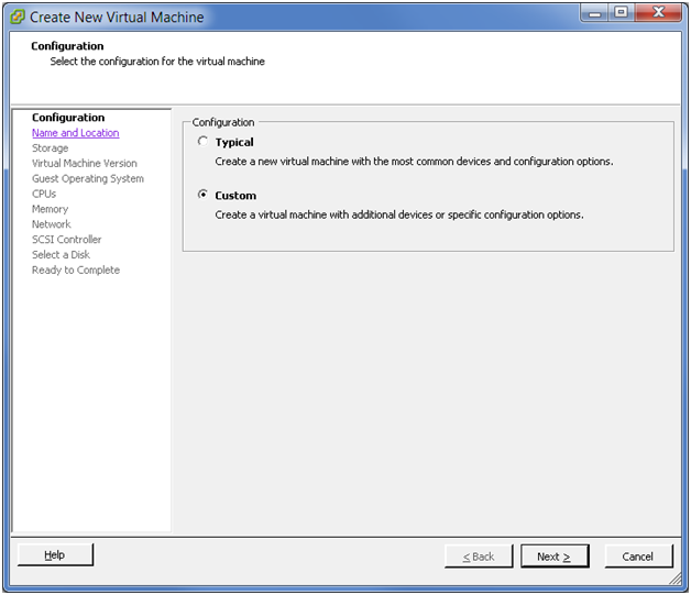
On the Configuration page, select , then click .
Figure 3-12 Create New VM: Configuration - Custom
-
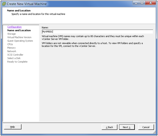
On the Name and Location page, select a name and location for the virtual machine, then click .
The name you enter is used as the virtual machine’s base name in the inventory and for the name of the virtual machine’s files. The name must be unique on the host server. Names are case insensitive and can be up to 80 characters long.
Figure 3-13 Create New VM: Name and Location
-
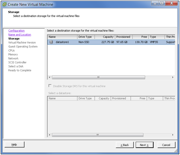
On the Storage page, select a destination datastore for the virtual machine files, then click .
For this example, select datastore1.
Figure 3-14 Create New VM: Storage
-
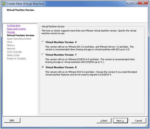
On the Virtual Machine Version page, specify the compatibility version desired for the virtual machine image, then click .
If the host supports more than one VMware virtual machine version, you can select a version for the virtual machine.
Figure 3-15 Create New VM: VM Version
-
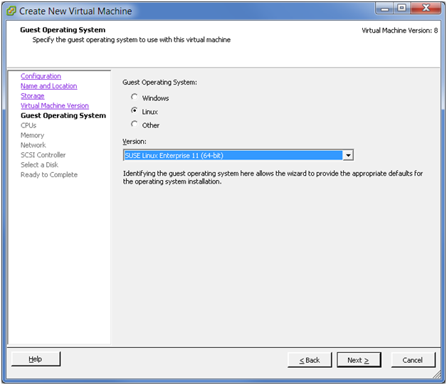
Specify the guest operating system and version to use with this virtual machine, then click .
For the OES Server, select Linux as the , then select from the drop-down list.
Figure 3-16 Create New VM: Guest Operating System
-
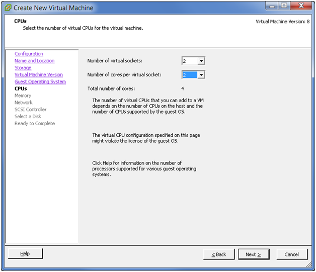
On the CPUs page, select the number of virtual sockets for the virtual machine, select the number of cores per virtual socket, then click .
The total number of cores is the number of cores per socket multiplied by the number of virtual sockets. The resulting total number of cores should be a number equal to or less than the number of logical CPUs on the host.
Figure 3-17 Create New VM: CPUs
-
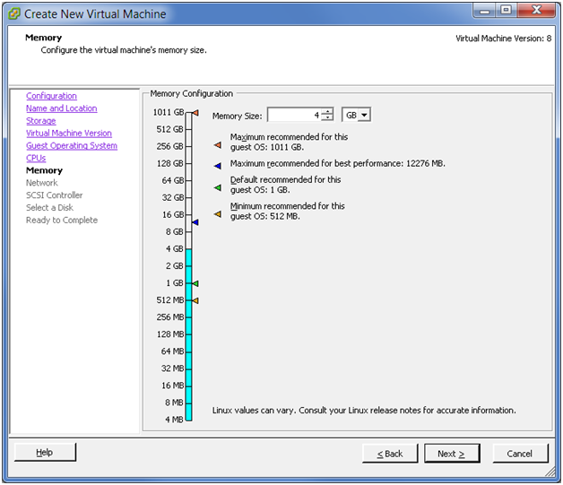
On the Memory page, specify the amount of memory that the guest operating system can use, then click .
The minimum memory size is based on the type of firmware used by the virtual machine:
-
BIOS firmware: 4 MB
-
EFI firmware: 96 MB
The maximum memory size for a virtual machine depends on the host’s physical memory and the virtual machine’s hardware version. The size must be a multiple of 4 MB.
Figure 3-18 Create New VM: Memory
-
-
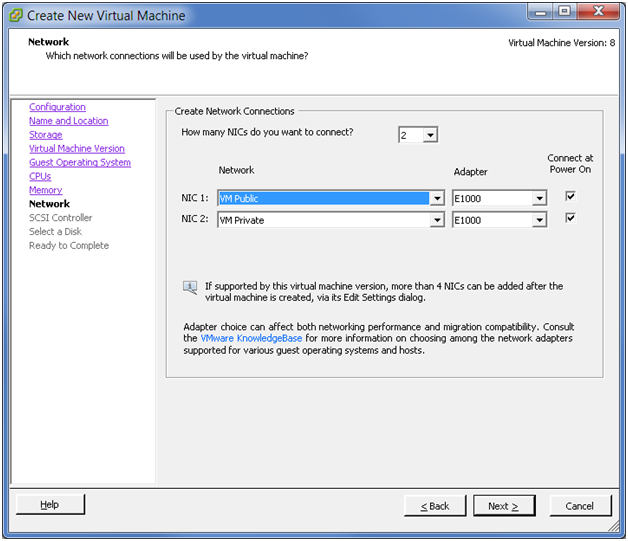
On the Network page, specify 2 as the number of virtual NICs to connect, specify the following values for each NIC, then click .
NIC
Network
NIC
Connect at Power On
NIC1
VM Public
E1000
(or as appropriate)
Selected
NIC2
VM Private
E1000
(or as appropriate)
Selected
For the public IP address, you can use any static public IPv4 address that is available to your company.
In VMware, a private NIC is a virtual NIC connected to virtual switch that is on a private network. You can have as many private NICs as the VMware host can handle. You can use any available private IP address to bond to the private NIC. For IPv4, the private IP addresses are 10.0.0.0 to 10.255.255.255, 172.16.0.0 to 172.31.255.255, and 192.168.0.0 to 192.168.255.255.
IMPORTANT:NCS does not require private NICs or private networks, whether you are using virtual or physical environments.
There are perceived advantages and disadvantages for using private NICs. With private NICs, your NCS inter-node traffic can be kept internal and separate from data access traffic, which keeps it more secure and provides separate bandwidth. However, the separation could create a scenario where NCS traffic moves smoothly while data access traffic is down. Some administrators prefer to deliberately combine NCS and client traffic together to avoid this kind of problem.
Figure 3-19 Create New VM: Network
-
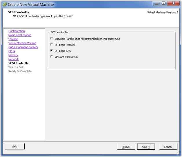
On the SCSI Controller page, select the SCSI controller type as (the default for SLES 11 64-bit), then click .
The wizard preselects the correct default controller based on the guest operation system you selected on the Guest Operating System page.
Figure 3-20 Create New VM: SCSI Controller
-
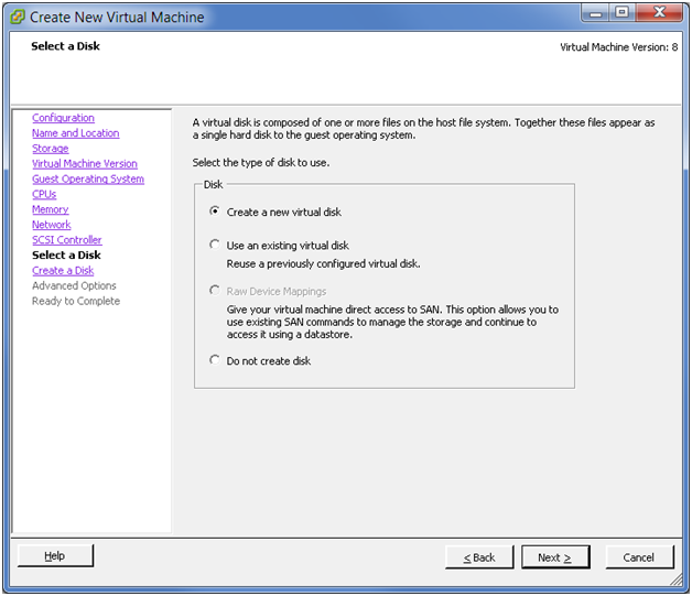
On the Select a Disk page, select as the virtual disk type to use for the system device, then click .
Figure 3-21 Create New VM: Disk
-
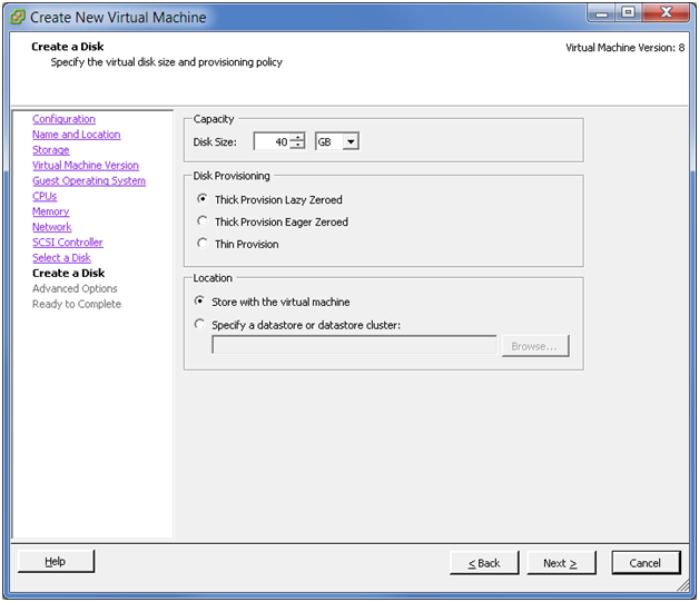
On the Create a Disk page, specify the following information for the virtual disk, then click .
-
Disk Size: Specify the amount of space to use for the system device. For example, 40 GB.
-
Disk Provisioning: Select .
The specified disk space for the virtual disk is allocated at create time. Any data remaining on the physical device is zeroed out on demand at a later time on first write from the virtual machine.
-
Disk Location: Select .
Figure 3-22 Create New VM: Create a Disk
-
-
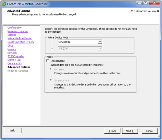
On the Advanced Options page, specify the advanced options to use for the virtual disk, then click .
-
Virtual Device Node: Select from the drop-down box.
-
Mode: Deselect the check box.
Figure 3-23 Step 15 (Advanced Options)
-
-
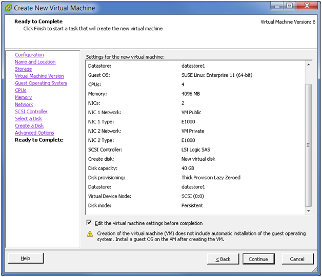
On the Ready to Complete page, review the configuration settings, select , then click .
Figure 3-24 Create New VM: Ready to Complete
-
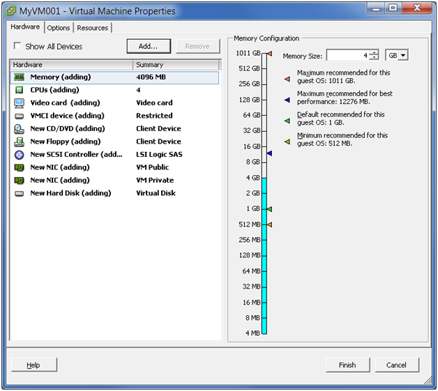
On the Hardware tab of the Virtual Machine Properties page, review the hardware properties and edit the VM settings before you complete the virtual machine creation.
The procedures in this step describe how to modify the following settings:
-
Add the shared storage.
-
Add a CD/ROM device if you are installing from the host CDROM device or from an ISO file.
-
Remove unwanted hardware, such as the floppy disk.
-
Set the BIOS screen to appear on the next reboot.
-
Change the MAC address setting to and use static MAC addresses.
-
Add dedicated NICs.
Figure 3-25 Create New VM: VM Properties
-
Add the shared storage that you created and mapped in Section 3.7, Preparing Shared Storage.
Repeat the following procedure for each shared hard disk that you want to add to this virtual machine:
-
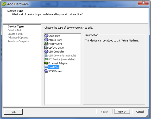
On the Hardware tab, click , select as the then click .
You can also select , then click .
Figure 3-26 Add Hardware: Add> Device Type > Hard Disk
-
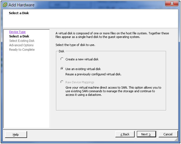
On the Select a Disk page, select , then click .
Figure 3-27 Add Hardware: Select a Disk
-
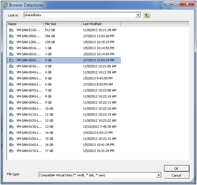
On the Select Existing Disk page, click . In the pop-up browser, locate the datastore, select the disk you want to add from the datastore, then click . On the Select Existing Disk page, click .
As a best practice for consistency, add the SBD disks first, then add the data disks. For the first hard disk you add, select one of the disks you prepared for use as an SBD. For the second hard disk you add, select the second disk that you prepared for the SBD. Thereafter, you can add data disks in your preferred order.
Figure 3-28 Add Hardware: Select Existing Disk
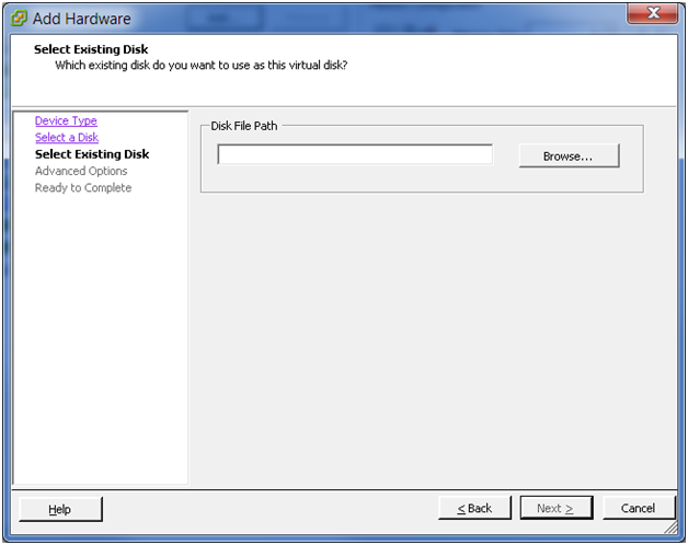
Figure 3-29 Add Hardware: Browse Datastores
-
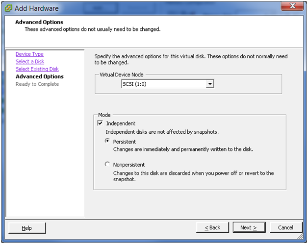
On the Advanced Options page, specify the following values, then click .
-
Virtual Device Node: Select (or the default node value offered as appropriate if you have added multiple disks) from the drop-down box.
-
Mode: Select the check box, then select .
Disks in persistent mode behave like conventional disks on your physical computer. All data written to a disk in persistent mode are written permanently to the disk.
Figure 3-30 Add Hardware: Advanced Options for the Existing Disk
-
-
On the Ready to Complete page, review the selected options, then click .
Figure 3-31 Add Hardware: Ready to Complete Add Existing Hard Disk

-
Repeat the previous steps for each shared hard disk that you want to add.
-
-
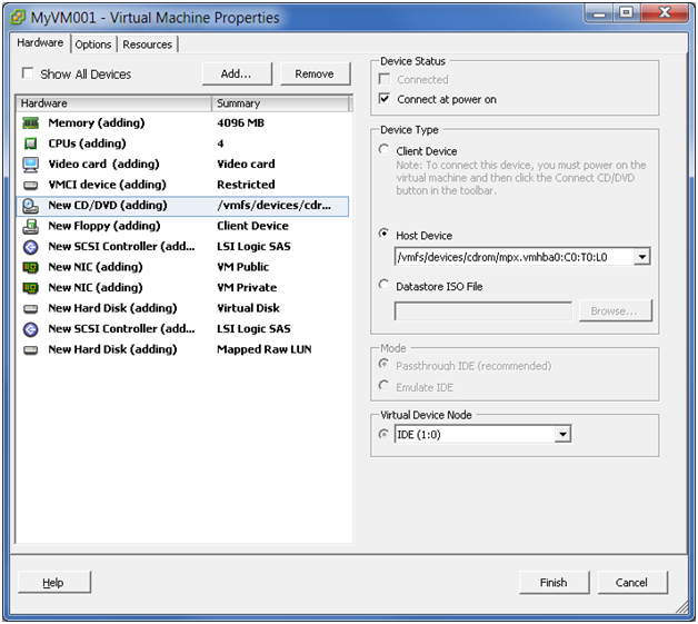
On the Hardware tab of the Virtual Machine Properties page, add a CD/DVD device, then set its properties.
-
Device Status: Select the check box.
-
Device Type: Use one of the following resources:
If you are installing from a DVD, select , then select the path of the device from the drop-down list. In the Figure 3-32 example, the path is /vmfs/devices/cdrom/mpx.vmhba0:C0:T0:L0.
If you are installing from a DVD ISO file, select , then browse to locate and select the file.
-
Virtual Device Node: Select the device node from the drop-down list, such as .
Figure 3-32 Create New VM: CD/DVD Disk Properties
-
-
On the Hardware tab of the Virtual Machine Properties page, remove unwanted hardware, such as the floppy disk. Select the object, then click .
-
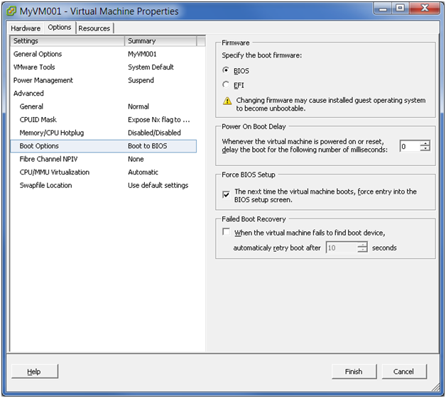
On the Options tab of the Virtual Machine Properties page, review the settings. If you need to set the BIOS for the virtual machine, select the Force BIOS Setup check box.
The next time the virtual machine boots, it is forced into the BIOS setup screen.
Figure 3-33 Create New VM: Options > Boot Options
-
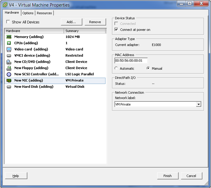
On the Hardware tab of the Virtual Machine Properties page, select the VM Private NIC, change the setting to , then type the static MAC address.
Figure 3-34 Create New VM: Hardware > NIC > Manual MAC Address
-
On the Hardware tab of the Virtual Machine Properties page, add dedicated NICs.
-
On the Hardware tab, click .
-
On the Add Hardware page, click .
Figure 3-35 Add Hardware: Choose PCI Device
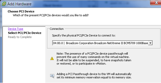
-
On the Chose PCI Device page, specify the physical NIC to use for the NIC.
-
Click .
-
-
Click .
-
-
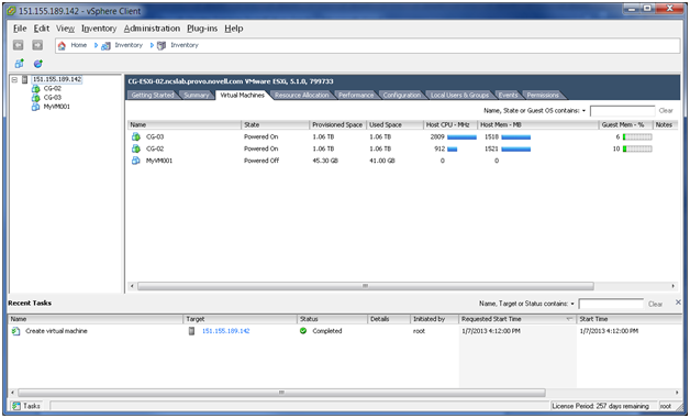
In the vSphere client, select > , then verify that the newly created virtual machine appears in the VM list of the vSphere client.
Figure 3-36 VM List in the VSphere Client
-
(Optional) View a list of the files created for the virtual machine. In a terminal console, go to the location that you specified for the virtual machine, then enter
ls -l
For example:
#1 root@CG-ESXi-02:/vmfs/volumes/509d3948-7ed53294-d0b3-984be1751d14/CG-02 # ls -l
-rw-------    1 root     root     0            Nov 27 21:54 CG-02-8ddbb415.vswp
-rw-------    1 root     root     42949672960  Nov 27 22:37 CG-02-flat.vmdk
-rw-r--r--    1 root     root     8684         Nov 27 22:34 CG-02.nvram
-rw-------    1 root     root     466          Nov 27 21:55 CG-02.vmdk
-rw-r--r--    1 root     root     0            Nov  9 19:21 CG-02.vmsd
-rw-r--r--    1 root     root     6862         Nov 27 21:54 CG-02.vmx
-rw-------    1 root     root     0            Nov  9 19:21 CG-02.vmx.lck
-rw-r--r--    1 root     root     256          Nov  9 19:21 CG-02.vmxf
-rw-r--r--    1 root     root     6862         Nov 27 21:54 CG-02.vmx~
-rw-r--r--    1 root     root     2662757      Nov 27 22:04 vmware.log
-rw-------    1 root     root     8566144      Nov  9 19:21 vmx-CG-02-2379985941-1.vswp