4.2 Configuring Your System
4.2.2 Configuration Steps
These configuration steps are recommended as a guide to assist with customizing the application to suit the service environment. These are the minimum steps required to enable your system. They require access to the Administrator and Supervisor views.
The following procedure covers editing the logged-in User account details and ensuring that this User has all the relevant privileges to achieve what is required to configure the system. It then details the steps to enable the system to work with email, setting the privileges for how Customers and Technicians can interact with the system, and how requests and the system will behave. This is defined within the tabs.
The User then has the option to customize the look and feel of the system, although this can be done later, if preferred. The next step is to create Customers and Users in the system.
For details on various Roles and Portal views, see the following in the ZENworks Service Desk - Getting Started guide:
-
User Roles
-
Portal Views
Moving to the Supervisor Role, the User then configures the day-to-day elements within the application, which are part of creating and managing requests. This includes setting the time frames for managing requests and defining trigger points for escalations by configuring SLAs (Service Level Agreements); detailing the steps a request will move through by customizing Workflows, which includes setting the stages of the Workflow where timers trigger automatic warnings and escalations; defining the Teams of Technicians who will be associated with the customized Workflows and SLAs.
With the basic elements in the system now in place, the User then moves to the tab to customize the Configuration Management Database (CMDB). This part is often considered the most complex part of configuring the system, because this is where the service environment, including physical and service Items, is mapped into the system with associated relationships. When you design the CMDB, the templates for all the different Item Categories are first created. These are refined as Item Type templates, with these two templates used to define the information recorded against each Item and classification of issues that can be associated with each Item when requests are logged by Customers.
After the CMDB structure is defined, Items are imported via AMIE or a .csv file. This is when the Items are associated with Customers or Organizational Units, who can log requests against the assigned Items.
Customizing the Default Supervisor Access
The default supervisor can create worklfows, SLAs, and teams. First identify the default supervisor and grant him the required permissions and roles.
To grant permission to the user:
-
Click the tab
-
Select the appropriate user
-
Select all the processes.
For details, see
Configuring Email Setup and Email Messages
This step allows the system to manage requests via email. After you finish filling in the information in the and tabs, the content for automated email sent by this system can be customized.
To set the email functionality details:
-
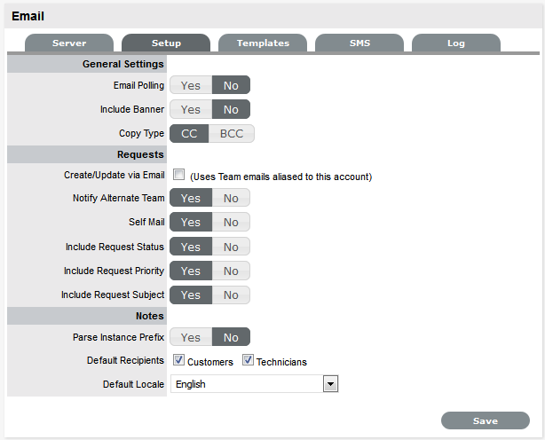
Select .
-
Define the settings in line with your organizational requirements:
Email Polling Enable Email Polling to allow the application to check for new email received in the mailbox on the incoming server defined within the tab. For new messages that are received, the system sends an acknowledgement message to the sender. System-generated messages are customized within the tab. This option is locked down if the option is selected.
Interval Specify the time period the system uses to check the incoming server for any messages sent to the support system.
Include Banner Select to include a banner within email sent from the system. The banner is derived from .
Email Errors When this option is enabled, details of any system errors occurring while the application is running are sent to the development lab.
Copy Type For email sent within requests, define if the Technician is to be copied or blind copied on the correspondence.
Create/Update via Email Select this option to enable requests to be created from emails addressed to the support system and Team addresses aliased on the email server. Email Polling is locked down to when this option is selected and the Accept Anonymous option is displayed.
Accept Anonymous When this option is enabled, the system creates requests from email received from email addresses that do not exist in the application's database.
Notify Alternate Team When this option is enabled, and if there is more than one Team created for a Process, the field is displayed within the tab of a request. Members of the Alternate Team are notified relative to the settings defined for the , and for , if is selected in the screen.
Self Mail When this option is set to , new Notes created by a Technician or Customer are also sent to them when they save the Note.
Include Request Status When this option is enabled, the system includes the request Status within the Email Subject line of any correspondence sent from the system regarding a request.
Include Request Priority When this option is enabled, the system includes the request Priority within the Email Subject line of any correspondence sent from the system regarding a request.
Include Request Subject When this option is enabled, the system includes the content from the Subject line of a request within the Email Subject line of any correspondence sent from the system regarding a request.
Parse Instance Prefix The Instance prefix is used to process email correspondence from multiple instances. If this is not required, set the option to .
Default Recipients Within the new Notes editor of requests, the default email settings can be defined for the recipient groups. Define the groups who are more likely to be sent every new note that is related to a request.
Language Set the default language file to be applied to email correspondence. The content for automated email sent from the system for languages other than English, is defined within the > tab.
-
Click .
When the option is enabled, the system creates requests from email received from email addresses not recorded in the application. This process is managed by assigning the System User as the Customer, and adding the original sender to the email address list in the Notify section.
Enabling this option increases the likelihood of spam email being converted into unwanted requests in the system. Email administrators should ensure that spam filtering is performed prior to the request being received in the Inbox polled by the application. It is not the function of the service management tool to monitor, parse, or filter emails prior to the creation of records based on the contents of the target Inbox.
Enabling System Privileges
At this stage, you should review each option in the , , , and tabs within the sub-menu option. If you are unsure about what an option refers to, select the Help button on the system UI to display the relevant page of the User Guide. Before importing Customers and User via an authentication server, ensure that you set the appropriate Time Zone within the tab.
-
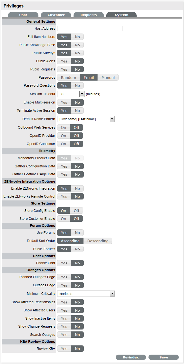
Select . The tab is displayed.
-
On the tab, define the settings:
Host Address The details of the machine hosting the application.
Edit Item Numbers Allows users to edit the identification number of an Item.
Public Knowledge Base Allows access to the Public Knowledge Base on the login page.
Public Surveys Provides access to Public Surveys on the login page.
Public Alerts Alerts with the visibility defined as Everyone are made available on the login page.
Passwords When LDAP or Active Directory Authorization is not used, internal authentication is used. To define the password type to be used by the system, select one of the following:
-
Random: The system generates a random string whenever a password is reset.
-
Email: The User’s email address is used as the password.
-
Manual: Allows the User to manually create a password.
Session Timeout The number of minutes the system waits before terminating idle sessions. Ensure that the session timeout on the server hosting the application is equal to or greater than the option defined in the System Privileges.
Enable Multi-session Enables ZENworks Service Desk users to log into multiple accounts on the same site, simultaneously.
Terminate Active Session When this option is enabled, if a User attempts to log into the system when they already have an active session, they are prompted to end the active session to allow for the new login.
Default Name Pattern Select the order for names being displayed in the system, when the First and Last Name are shown together on a screen.
Outbound Web Services When this option is enabled, request Workflow States and Item Lifecycle States can be assigned a listener, which allows these details to be updated in external systems.
OpenID Provider Enables the system to function as an OpenID Provider for User authentication across network resources, as the user authentication source.
The OpenIDProvider URL should be:
The Protocol should be set to http or https and the server details should include where the system is hosted.
OpenID Consumer Enables the system to delegate authentication of Users and Customers to one or more OpenID Providers (such as, Google or Yahoo). OpenID Providers that are to be used as delegates are configured in the tab.
Use Forums This option enables and disables all Forums within the system.
Default Sort Order Sets the default Forum Topic sort order to either ascending or descending.
Public Forums This option enables Public Forums to be viewed from the login page and does not require an account to view.
Enable Chat Select to activate Chat facility within the application.
Chat Request Assignment Set this option to if Customers are to be restricted to chatting only with the Technician assigned to their Request. Set it to to allow Customers to chat with any member of the Team assigned to their request.
Default Technician Availability Sets the default availability for chat status in newly created Technician Account information screens.
Planned Outages Page A link to the Planned Outages page is displayed on the login screen. Outages can be set within Configuration Item properties to schedule when the item is offline.
Outages Page A link to the Outages page is displayed on the login screen.
Minimum Criticality Defines the Minimum Criticality required for Items to be displayed on the Outages pages.
Show Affected Relationships Enables an Item from the Outages page to show the Item's Relationships.
Show Affected Users Allows the Item owner's details to be displayed on the Outages page.
Show Inactive Items Displays inactive Items on the Outages page. An inactive Item is an Item that is currently not in use by the organization.
Show Change Requests Allows Customers to view Change Requests related to Outages displayed in the Customer Portal.
Search Outages Enables Outages to be searched by using the Customer email addresses or Item number.
Review KBA When this option is enabled, a field is displayed in the KBA Information screen. Set the default number of days between reviewing KBAs should be set and the number of days before the review date for an Alert Reminder.
-
-
Click to enable the or click to disable it.
-
Click to save configuration settings.
All Outages options applies only to Service Manager.
The button at the bottom of the System Privileges page is used to re-build the system index. If the search engine appears to be failing text searches, this process re-creates the index. The indexing rebuild runs as a background process.
The following content will be re-indexed:
-
Knowledge Base
-
Forums
-
All requests
-
Items
Customizing Banners and the Welcome Page Message
This can be done now if the images are available. Alternatively, return to this step at a later stage.
The Customize menu allows the Administrator to brand the application where system banners can be replaced with the appropriate organizational banners. Graphics included should be .PNG images. The Application Banner should be 200 x 60 pixels and all other banners should be 500 x 70 pixels.
-
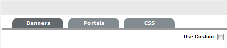
Select .
Application Visible on the Log in page of the system.
User Visible in the portals for Supervisor, Technician, Administrator, Partner, Finance and Manager Users.
Public/Email Displayed on public portals for Knowledge, Outages, Surveys and Forums. This banner is also included in emails when the Setup > Email > Setup option of Include Banner is set to Yes.
Customer Visible in the Customer Portal. Banners for Partner Organizations can be uploaded in the Banners tab of the screen. This will override the system Customer Portal banner for Customers associated with the Partner Organization.
-
To use Custom Banners, select the checkbox at the top of the screen.
-
To upload a new banner, click . A window with a browse function appears.

-
Browse to the location of the image and click
 .
.The image will be uploaded.
-
Repeat the process until all banners have been replaced.
-
Click .
All Public Access home page messages can be fully customized under the Messages tab.
Knowledge of HTML is required to edit this section. Links to documents and downloads may be added. The home page messages can be customized for:
-
Alerts
-
Forums
-
Knowledge Base
-
Login Page
-
Public Outages
-
Planned Outages
-
Surveys
-
Customer Portal Welcome Page
-
Select .
-
Select the hyperlink. The HTML editor appears.
-
Edit the message as required.
-
Click .
Creating Customers and Users
Customers and Users include Supervisor, Technician, and Partner accounts.
NOTE:To associate Organizational Unit information with Customers or Users, you can use the tab. If the import includes the name of the Org Unit that matches what is recorded in the system, the details from the information recorded internally are applied to the Customer or User.
There are several ways to authenticate users of the service management application. By default, the system uses its internal authentication mechanism, but there is also the option to authenticate against a Directory Server or use OpenID Providers.
If you are using an authentication server, move to the tab where you can configure Internal Authentication, Active Directory integration, or LDAP integration.
Internal Authentication
Using internal authentication requires the Administrator or Supervisor to create accounts for all User types by entering the contact information, access levels, and password. This information is then saved to the system database.
The typical case for using Internal Authentication is where there are few Users, or in an environment that has no pre-existing directory server. Usually, the Administrator would configure the User accounts prior to announcing the system is operational, and from that point on, maintain the accounts as necessary.
OpenID Providers
OpenID is a decentralized process to verify a Customer's or User's online identity. It addresses the single sign-on issue by not relying on a centralized Web site to confirm a User's identity. The system can be enabled to be an OpenID consumer, which provides seamless authentication between third-party authentication utilities and the service management system. OpenID Providers are configured within the tab, and Customers or Users that have accounts with the configured OpenID Providers can log into the system by selecting the relevant icon on the Login page.
Directory Server Authentication
The system allows the Administrator to connect to a Directory Server for User authentication purposes. This removes the need to create User accounts because it allows the application to synchronize User accounts and access levels with the existing Directory Server. It has the added benefit of allowing the Administrator to work with existing infrastructure.
Directory Server Groups (External Authentication)
Roles are used to grant access within the application. Users must be assigned to Groups on the directory server that correspond to the Roles within the support system. Group members are assigned Roles and access levels within the service management tool.
If you are creating accounts directly in the system (that is, using internal authentication), go to the tab.
Setting Up Service Level Agreements
Move to the Supervisor view by clicking the link next to the name of the logged-in User.
If these are unknown at this time, the system includes a default SLA that can be used.
The goal of Service Level Management is to maintain and improve the alignment between business activities and IT service quality. This is achieved through the following cycle:
-
Agreeing on service level expectations and recording them in Service Level Agreements (SLAs)
-
Monitoring the service provided
-
Reporting actual service delivery results
-
Reviewing IT service delivery results in relation to the SLA, and adjusting accordingly
A Service Level Agreement (SLA) is a formal, negotiated contract that outlines service level expectations and clarifies responsibilities between the Service Desk and its Customers. When unacceptable levels of service are noted throughout the service cycle, action can be taken to re-align expectations with actual service delivery results.
Within the system, SLAs are specific and time-based in order to help monitor and report on performance. They can be applied to any of the following elements within the application:
-
Customers
-
Organizational Units
-
Items
Only users who have the Service Level Management role can create or modify SLAs
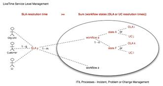
SLAs are incorporated in the support process when a new Workflow is created. An SLA is assigned to a Workflow and specifies the expected resolution time for a request. To successfully meet SLA expectations, the system allows the Service Desk to associate each Workflow State of a request with an Operational Level Agreement (OLA) or Underpinning Contract (UC).
An OLA is an internally negotiated document that identifies the service level expectations between the Service Desk and the Technical Support Teams. An Underpinning Contract enables the Service Desk to monitor and maintain control of requests that are forwarded to external service and support providers.
To ensure that an SLA resolution time is met, the sum of the resolution times for each of the OLAs or Underpinning Contracts assigned to a Workflow Lifecycle must be less than or equal to the SLA resolution time.
When a request is logged with the Service Desk, the request adopts the SLA that has been assigned to either the Item, Customer, or Organizational Unit. If an SLA has not been allocated to any of these elements, the SLA assigned as the system default within the tab is automatically applied to the request.
The SLA allocated to the request determines the Workflow options made available for the lifecycle of the request. The Workflows listed are assigned the same SLA as the request. Before saving the request, the User can adjust the system assigned Workflow if more than one option exists.
Creating Operational Level Agreements and Underpinning Contracts
This is more than likely an advanced system configuration step at this point, or it might not be relevant to the service organization. However, if OLAs or UCs are in place in the service organization, they can be mapped into the system now. Alternatively, they can be added later.
Operational Level Agreements (OLAs)
An OLA is an internally negotiated agreement that identifies the service level expectations between the Service Desk and the Technical Support Teams. OLAs are applied to Workflow States and allow the Service Desk to successfully meet service level expectations. This is achieved by associating an SLA to a Workflow and then assigning, where relevant, OLAs or Underpinning Contracts to separate stages of that Workflow. SLA targets for Response, Restoration, and Resolution time must be greater than or equal to the combined OLA and UPC times for each of these targets, to ensure that service level breaches do not occur.
Creating a new OLA
-
Select .
-
Click .
-
Enter the following details for the OLA in the tab:
Name The name to identify the OLA.
Review Date Details are completed based on the Admin default settings but can be edited by the User. An Alert is sent based on the default days set in the field in .
Pause on SLA Holiday This option is only displayed if the option has been enabled within the tab.
Enable this option if the OLA is to be adjusted on designated public holidays, when an associated SLA has the option enabled. The public holidays are defined within the screen and associated with requests via the assigned Technician and the associated Country.
Customer Timezone When this option is enabled, OLA times displayed within the Technician request view use the Customer timezone.
Timezone This option is visible when Customer Timezone is not set and all SLA dates are calculated based on the Timezone set within this field. This is especially applicable for User Work Hours and Blackouts, which also impacts the SLA Reports.
SLM Name and Email Use the Find Service Level Manager search option, to enter the contact details of the Manager who monitors the performance of the OLA.
-
Adjust the Review Date, if necessary (A reminder Alert is sent to the SLM, based on the default days set in ).
-
Select the option, if relevant.
Apply this option if the User is to view OLA due dates by using the Customer Timezone.
-
Search for and select a Service Level Manager.
A Service Level Manager (SLM) is a User that has the Service Level Management Process.
-
Move to the tab.
-
Fill in the following information:
Targets Select if the OLA is to apply across Incidents, Requests, Problems, and Change Management. If the OLA is specific to a Process, select and choose a Process from the drop-down list.
Interval Define if the time is to be calculated in Hours or Minutes.
Priority Urgent, High, Medium, and Low
Initial Response The maximum time the Customer would wait from the point of request creation before receiving a Note update for a Technician. The Response trigger is stopped when a Note has been added to the request by the assigned Technician and an email is sent to the Customer. If the Response Time is reached without a Note being added, the request is escalated.
Restoration Time The maximum time the Customer should wait from the time the request was created until a workaround or temporary fix has been implemented. The Restoration trigger stops by assigning the request a Workflow State that has the option set to . By default, this Workflow State is Open - Restored.
Resolution Time The time taken from the point of request creation until the request is moved to a Workflow State with the OLA Resolution option set to . Any of the default Workflow Exit States stop the Resolution Timer.
Notify Override If the system is to override the default notification method set for a request when the Priority being edited is assigned to a request, select this option.
Notification Type Set Email or SMS as the type of notification when the override action is applied to a Priority.
Reminder Sends a reminder email to the Technician when the defined percentage of time elapses for a Response, Restoration, or Resolution target that has not been met on a request. Can be set up to 200% of the OLA. Alert intervals are not cumulative.
Warning Sends a warning email to the Technician when the defined percentage of time elapses for a Response, Restoration, or Resolution target that has not been met on a request. Can be set up to 200% of the OLA.
Escalation Escalates the request to a higher escalation layer when the defined percentage of time elapses for a Response, Restoration, or Resolution target that has not been met on a request. Can be set up to 200% of the OLA. The Service Level Manager is also notified when an OLA is breached.
24x7 Do not amend if the OLA is to apply 24 hours a day, 7 days a week.
Normal Support Select if service hours are to be defined for the OLA. When this option is selected, define the service hours by either selecting a template (Templates are configured by the Administrator in the tab) or manually define the days and time by making selections within the drop-down lists.
-
Add one or multiple Warning Alerts, if required Trigger intervals are not cumulative.
In the default OLA for Warranty, the Urgent default times of 6, 12, and 24, indicate 6 hours for the Response stage, 12 hours for Restoration from initial creation, and 24 hours to reach the Resolution from initial creation.
-
Define the support hours.
Within 24 X 7, if the OLA's urgent field is set to 6 hours, and an urgent request that uses the OLA is created at midnight in the assigned Technician's time zone, those 6 hours will expire by 6:00 a.m. This is the option to use if your support is staffed 24 hours a day.
Normal support ensures that request timers do not run when Technicians are not available. For instance, if the support hours are 9:00 a.m. to 5:00 p.m. and the SLAs reflect this, the urgent request timer does not start until 9:00 a.m. the following business day and would expire at 3:00 p.m.
-
Click .
-
Click .
-
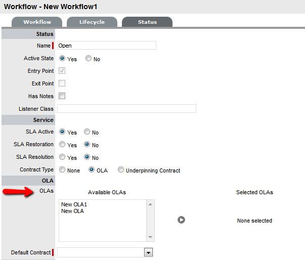
Next, associate the OLA with a Team within the tab of the Team Information screen. The OLA is also available within the OLA options displayed when OLA is selected as a Contract Type option within the Workflow Status editor screen.
-
Move to the tab. The tab lists the Workflow stages that are assigned to the OLA.
-
Move to the tab. The tab displays the Team Names and Processes that are assigned to the OLA.
Assigning an OLA to a Team
OLAs are assigned to support Teams when Teams are created or edited. To view an OLA Team assignment, select an OLA to display the list of assigned support Teams within the tab. The Team Lead and the Process the Team supports are also visible.
OLAs and Blackout Periods
If a request is assigned an OLA State and the request's SLA is in a Blackout Period, the OLA adopts the SLA Blackout Period. This means that the OLA timers stop until the Blackout Period has elapsed.
4.2.3 Customizing or Creating Workflows
The system includes default Workflows across all Processes. At this point, the default Workflows might be sufficient, or they can be customized to suit the service organization requirements. Alternatively, new Workflows can be created from scratch.
Incident and Problem Workflows
Workflows define the sequence of States to be followed by requests logged with the application. Within the system, an unlimited number of Workflows can be configured for Incident and Problem Management.
When deployed, the system includes one fully customizable Workflow for each of the Incident and Problem Management processes. These can be used immediately, or they can be edited to more comprehensively reflect the support service requirements.
SLAs and Workflows
Each Workflow can be associated with one or more SLAs. The SLA provides the contract time that must be met by requests using the Workflow.
For example, if the Service Desk uses one Incident Workflow, which has multiple SLAs assigned to it, logged Incidents follow the same Lifecycle but the time allowed within each stage is based on the SLA contract requirements. The SLA assigned to either the Item, Customer, Organizational Unit, or Incident determines which Workflow is selected for the Incident.
Editing Default Incident and Problem Workflows
Incident and Problem Workflows can be configured to reflect the organizational Service Desk requirements for these processes. The default Workflows include States that are used by the business logic of the application to maintain control of the request Lifecycle.
The Selected States used by the application, as indicated by an asterisk, should not be removed from the Workflow Lifecycle. However, other Available States can be added to the Selected States list.
The following list contains the default Incident and Problem Workflow States. The * denotes the system States.
Cancelled Used to cancel a request when it is no longer to be worked on.
Cancelled Unpaid* Used by the system from the Pending - No Contract State when Contracts and Invoices are enabled.
Closed Resolved Used when the request has been resolved. This is the Default Closed State for the Incident and Problem Workflows. This marks the end of SLA timing and is used when measuring SLA times for Reports.
Closed Restored Used when the request has been closed and the service restored for the Customer. This marks the end of SLA timing and is used when measuring SLA times for Reports.
On Hold Used when the request is on hold. By default, this State stops SLA timing.
On Hold - Client Action Awaiting a response from the Customer. When a Note is added to the request by the Customer, the system changes the status to Open.
On Hold - Pending Approval* An Incident automatically moves to this State when the button is used for sending an Incident Note. This means the CloseRequest email is sent to the Customer, asking them to verify the proposed solution. If the Customer does not respond to the email, the request is automatically closed by the number of days set within the Handshaking Privilege. (The email handshaking option is set by the ) By clicking the URL provided in the email, the Customer ensures that the request retains an open and active state.
On Hold - Process Escalated* A request moves into this state when a Problem or Change has been created within the tab of the request. The timer stops and there are no future States because the request is closed when the related Problem or Change is closed.
Open Used to indicate that the request is currently open.
Open Restored Used to identify that initial service to the Customer has been restored, or a Workaround is in place but the request is not resolved. This State stops the initial Response Timer if a Note has not been added to the request by a Technician.
Pending The default first State for new requests.
Pending - No Contract* Used when a request is created but there is no active Contract. A Contract needs to be created for either the Customer, Incident/Problem, Item, or Organizational Unit.
Do not use this State as the Default Open State for a Workflow.
Editing Template Workflows
Prior to creating or editing existing Workflows, the preferred Workflow Lifecycle should be mapped externally to the application.
If States are to be added or removed from the Workflow, all changes should be made to the list within a Workflow's tab, prior to mapping the Lifecycle. This ensures that all relevant status options exist in the field, for allocation to the Previous and Next Workflow States.
After the Workflow Lifecycle has been defined, edit an existing Workflow by using the following procedure:
-
Select . The Workflow screen appears.
-
Click the Workflow name hyperlink to modify or duplicate an existing template. Or, select to create an entirely new Workflow.
The tab appears.
-
Define the Name, select the Process, and set the default Open and Closed States for the Workflow.
The States available within these lists are all those marked as an Entry or Exit point in the tab.
-
Complete the details of a new Workflow. Enter the Name, select the Process and enter a Description and click .
-
In Edit Mode amend relevant details within the Workflows tab:
-
Workflow Name: Specify a relevant name for the Workflow.
-
Process: Select the process type of Incident or Problem Workflow from the drop-down options.
-
Default Open Status: The open State that a request adopts when it is assigned the Workflow.
-
Default Closed Status: The closed State that indicates the request has reached the end of the Workflow Lifecycle.
-
Email Note Action: This applies to requests that are in an non-active SLA State (that is, here the SLA Active option is set to ). The option selected here determines the system behavior, for an SLA inactive request, when an email is received from a Customer.
-
Do Nothing: The status of the request remains the same and the SLA timers are not re-activated. The email is added as a Note, and also sent to the Technician.
-
Update Status: The status of the request is changed to an SLA Timer Active state, the email is added as a Note and it also sent to the Technician.
-
-
Update Status to: This field is displayed when the option is selected for the field. It allows the User to set a Next State, which is defined as an SLA Timer Active State, where a request moves after an email has been received from a Customer regarding a request in an inactive SLA State.
-
SLA: Allows the User to assign an SLA to govern the lifecycle period of the Workflow. One or more SLAs can be associated with the Workflow.
-
Description: Defines the purpose of the Workflow.
-
-
Use the option to change or add SLAs assigned to the Workflow.
Click
 to access the complete list of SLAs in the system.
 -
Edit the brief description that explains the purpose of the Workflow, if required.
The field is visible when OLAs or Underpinning Contracts are associated with the Workflow States. It displays the accumulated amount of time of the OLAs or Underpinning Contract associated with the stages of the Workflow. This contract time cannot exceed the resolution time of the SLA assigned to the Workflow.
-
Click .
-
Select the tab to define Workflow States.
-
Edit the State details.
Click the box in the Workflow map or the name hyperlink in the table of States to display the Status information screen, or click to create a new Workflow State.
Name Name: System Required States, which are the States marked with an asterisk in the States Table, can be renamed if desired. For newly created States, specify a name.
Active State Assign for requests to be available in the tab by default, when they are assigned to this stage of the Workflow.
should be used for States where the User is actively working on the request or waiting for updates. generally applies to Workflow exit points and is only available by default within the relevant tab list view.
Entry Point An Entry Point is used to indicate the start of a Lifecycle. To make the state a Workflow Entry Point, select the check box. Because the Entry Point is the first state, the field removed.
Exit Point Select whether the State will be an Exit Point. An Exit Point is used to indicate the end of a Lifecycle. A Workflow can have only one Entry Point but multiple Exit Points.
Has Notes Allows the Supervisor to include instructions or add relevant details for requests that move into this State. The information is configured within the tab that is displayed when this option is enabled.
Listener Class This field is visible if the option is enabled in the tab. Complete this field, if assigning this State to a request is to trigger an event in an external system. This field should contain the name of a Java class that implements the interface com.livetime.ws.listenWorkflowListener that has been compiled into a .jar file and added to the LiveTime classpath. Contact support for further details.
SLA Active Links the status with timing set within SLAs and OLAs. When the option is set to , the SLA/OLA timers stop and the triggers for escalations and warnings do not fire.
SLA Restoration When timing is set by using SLAs and OLAs, the trigger is disabled when the request is moved to this state. indicates that a Customer has access restored or a temporary workaround. Reports on Restoration Time are measured from when the Restoration Time trigger is disabled.
SLA Resolution Allows the State selected to be used to mark the SLA Resolution Time. This is used in SLA reporting.
Contract Type Defines if the Workflow State will be managed by an internal (OLA) or external (Underpinning Contract) support agreement. If OLAs or Underpinning Contracts are assigned to a Workflow Lifecycle, the Workflow SLA Resolution Time cannot be exceeded by the sum of Resolution Times for all Contract Types assigned to the Workflow Lifecycle.
Assign SLM This field is displayed when a UPC is associated with the Workflow State. Use this field to define if the request ownership is to be maintained by the Assigned Technician or moved to the Manager of the SLA associated with the request.
Previous States If the State is not an Entry Point, use the arrow button to select from the and choose when this State appears as a drop-down menu option in the field.
Next States If the State is not an Exit Point, use the arrow button to select the Next States a request can move to, in the field of a request tab.
-
Delete the State or edit Name/Rename the State name.
-
Enter all State information up to the field.
-
Save the updated State details.
All States that are to be included in the Workflow should be added or re-named now.
After all States have been entered in the system, the mapping of the Workflow can be more easily achieved.
-
Continue to edit, add, or delete States until all relevant States exist for the Workflow.
-
Create the Workflow Lifecycle by assigning States to the transitional states of or .
To move Available States to the Previous State or Next State field, open the Status Details screen by clicking the State object in the Workflow map, or select the State hyperlink in the table beneath the Workflow map.
-
Assign a States to a or State.
For the Current Status select an option in the list and click the right arrow to move it to the field.
When a State is used as a Previous and a Next State, it allows a request to move forward and backward in a Lifecycle An Open State cannot have any previous States and a Closed State cannot have any Next States.
-
Click to return to the Workflow map and to access other States to build on the Workflow Lifecycle.
-
Repeat Steps 15 to 17 until all transitional stages of the Workflow have been mapped.
To successfully save a Workflow, the sum of the Resolution Time of the individual Contract Types assigned to each transitional state of the Workflow Lifecycle must be less than or equal to the Workflow's SLA Resolution Time.
-
Click .
The visual representation of the Workflow is displayed.
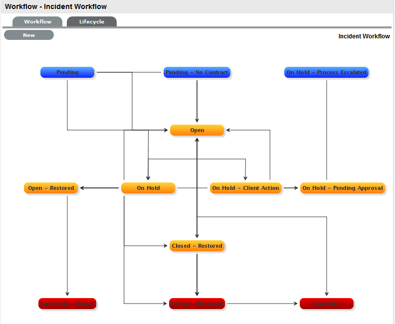
Workflow Map
The Workflow Map is a visual representation of the Workflow Lifecycle. The map displays the relationship between each Lifecycle State by using different colors to represent the type of Lifecycle State.
-
Blue: Indicates the Entry point of the Lifecycle
-
Red: Indicates the Exit point of the Lifecycle
-
Orange: Is a Transitional stage of the Lifecycle
Detailed information about a Lifecycle State can be accessed by clicking the field within the map.
Deleting a Workflow State
It might be necessary to delete a default State or a State that is no longer in use.
NOTE:A State cannot be deleted if it has been assigned to a request.
To delete an unused State:
-
Select
-
Click the hyperlink.
-
Click the hyperlink in the beneath the .
-
Click
-
Select .
The State is erased from the States list.
4.2.4 Service Request and Change Management Workflows
Service Request and Change Management Workflows define the sequence of States to be followed by Service Requests and Change Requests (RFCs) logged with the Service Desk. These Workflows are unlimited and fully configurable, to cover the diverse range of business change implementations required by an organization.
SLAs and Workflows
Each Workflow can be associated with one or more SLAs. The SLA provides the contract time that a Workflow must adhere to.
For example, if the Service Desk uses a Change Workflow, which has multiple SLAs assigned to it, Change Requests that use that Workflow follow the same Lifecycle but the time allowed within each stage is based on the SLA contract requirements. The SLA assigned to either the Item, Customer, Organizational Unit, or Request determines which Workflow is selected for the Change Request.
Approval States
Approval States in Service Request and Change Workflows provide the facility for Managers that have been assigned to the Approval State, to accept or reject Request activity. If a State has the Approval State option enabled, only Managers can be assigned to this State and it is not possible for other User Roles to also be assigned to the State. A Technician, Supervisor, or Partner User can also be assigned a Manager Role within the User Information screen, which allows them to be assigned as Managers to the Team and then to Manager Only Approval States.
Editing a Default Workflow
To edit a Service Request or Change Workflow:
-
Select .
The Workflows screen appears.
-
Click the Workflow name hyperlink to modify or duplicate an existing template or select to create an entirely new Workflow.
The tab appears.
Select the Process, then set the default Open and Closed States for the Workflow.
The States available within these lists are all those marked as an Entry or Exit point in the tab.
-
Complete the details for a new Workflow: Specify the Name, select the Process, and enter a Description, and click .
-
In Edit Mode amend relevant details within the tab:
-
Workflow Name: Enter a relevant name for the Workflow.
-
Process: Select from the drop-down options the process type of Change or Service Request Workflow.
-
Default Open Status: The open state that a Request adopts when it is assigned the Workflow.
-
Default Closed Status: The closed state that indicates the Request has reached the end of the Workflow Lifecycle.
-
Email Note Action: This applies to Requests that are in a non-active SLA State (that is, where the SLA Active option is set to No). The option selected here determines the system behavior, regarding an SLA inactive Request, when an email is received from a Customer.
-
Do Nothing: Means the status of the Request remains the same and the SLA timers are not re-activated. The email is added as a Note and also sent to the Technician.
-
Update Status: Means the status of the Request is changed to an SLA Timer Active State, the email is added as a Note and it also sent to the Technician.
-
-
Update Status to: This field is displayed when the Update Status option is selected for the Email Note Action field. It allows the User to set a Next State, which is defined as an SLA Timer Active State, where a request will move to after an email has been received from a Customer regarding a Request in an inactive SLA State.
-
SLA: Allows the User to assign a SLA to govern the lifecycle period of the Workflow.(See SLAs & Workflows above, for more information.)
-
Description: Defines the purpose of the Workflow.
-
-
Use the Find SLA option to change or add SLAs assigned to the Workflow.
Click
to access the complete list of SLAs in the system. Refer to the above section for more information regarding SLAs and Workflows.The Contract Time field is visible when OLAs and/or Underpinning Contracts are associated with the Workflow States It displays the accumulated amount of time of the OLAs and/or Underpinning Contract associated with the stages of the Workflow. This contract time cannot exceed the resolution time of the SLA assigned to the Workflow.
-
Edit the brief description that explains the purpose of the Workflow, if required.
-
Click .
-
Select the Lifecycle tab to create or modify Workflow States.
-
Click the State field in the Workflow map or State name hyperlink to display the Status information screen or, click New to create a new Workflow State.
-
Name: System Required States, the States marked with an asterisk in the States Table, can be re-named if desired. For newly created States, enter a name.
-
Active State: Assign Yes for requests to be available in the Home tab by default, when assigned to this stage of the Workflow. Yes should be used for States where the User is actively working on the request or waiting for updates. No generally applies to Workflow exit points and will only be available by default within the relevant Process tab list view.
-
Approval State: Sets the Status as an Approval State. This allows a Manager User to be assigned to this State, which enables them to approve or reject a Request when it moves into this stage of the Workflow. An Entry/Exit status cannot be an Approval State.
-
Item Editable: Select this option to allow the details of an Item to be edited when a Request is moved into this State . When this option is enabled for a Workflow State, inline_edit.gif is visible next to the Item Type link in the Summary tab of the Request.
-
KBA Approval: Enable this option as part of the KBA Approval process, which displays the Accept, Revise and Reject buttons for the User to publish, advise content revision or reject content. Enabling this option, removes the Next States fields and requires the User to define where the request will move to if the Accept and Reject buttons are selected. If the Revise button is selected, the Request will move to the "On Hold - KBA Rework" system state. See:KBA Content Approval
-
Entry Point: An Entry Point is used to indicate the start of a Lifecycle. To make the state Workflow Entry Point, select the Entry Point checkbox. As the Entry Point is the first state, the Previous States field will be removed.
-
Exit Point: Select whether the state will be an Exit Point. An Entry Point is used to indicate the end of a Lifecycle. A Workflow can have only one Entry Point but multiple Exit Points.
-
Has Notes: Allows the Supervisor to include instructions or add relevant details for Requests that move into this State. The information is configured within the Notes tab that is displayed when this option is enabled. Information and attachments included on the Notes tab, are displayed as a scroll-over when the Request moves into the State.
-
Listener Class: This field is visible if the Outbound Web Services option is enabled in the Admin>Setup>Privileges>System tab. Complete this field, if assigning this State to a request is to trigger an event in an external system.
This field should contain the name of a Java class that implements the interface com.livetime.ws.listenWorkflowListener that has been compiled into a jar file and added to the LiveTime classpath. Please contact support for further details.
-
SLA Active: Links the Status with timing set within SLAs and OLAs. When the option is set to No, the SLA/OLA timers stop and the triggers for reminders, escalations and warnings do not fire.
-
SLA Restoration: If the 'Yes' option is selected for SLA Restoration, it means that Requests that move into this Stage of the Workflow have met the SLARestoration Time.
-
SLA Resolution: If the Yes option is selected for SLA Resolution, it means that Requests that move into this Stage of the Workflow have met the SLA Resolution Time.
-
Contract Type: Defines if the Workflow State will be managed by an internal (OLA) or external (Underpinning Contract) support agreement. If OLA's or Underpinning Contracts are assigned to a Workflow Lifecycle, the Workflow SLA Resolution Time cannot be exceeded by the sum of Resolution Times for all Contract Types assigned to the Workflow Lifecycle.
-
Assign SLM: This field is displayed when an UPC is associated with the Workflow State. Use this field to define if the request ownership is to be maintained by the Assigned Technician or moved to the Manager of the SLA associated with the request.
-
Previous States: If the State is not an Entry Point, Previous States can be assigned to the Workflow stage. Highlight the relevant State and use the arrow button to move Available States to the Previous States field. These options designate the Workflow stages a Request can come from, before it arrives in this Workflow State.
-
Next States: If the State is not an Exit Point, Next States can be assigned to the Workflow state. Use the arrow button to select the Next States from the Available States. These options are included in the Next Action drop-down menu of a Request.
-
Accept State: (Visible when the Approval State or KBA Approval option is Yes.) Displays the States that a Request can move to when a Request action is Accepted. Select the appropriate State, for the system to automatically route the Request when the Accept option is selected. By default the system will assign Single for one Manager to Approve a Request.
If more than one Manager needs to Approve a Request, select Multiple or Percentage.
-
If Multiple is selected, set the number of Managers that are required to Approve the Request before the system will automatically apply the defined Accept or Reject State.
-
If Percentage is selected, set the percentage weighting that must be achieved by Managers voting before the system will automatically apply the defined Accept or Reject State.
-
-
Reject State: (Visible when the Approval State or KBA Approval option is Yes.) Displays the States that a Request can move to when a Request action is Rejected. Select the appropriate State, for the system to automatically route the Request when the Reject option is selected.
-
-
Delete the State if required, or Name/Rename the State.
-
Enter all State information up to the SLA Resolution field.
-
Save the updated State details:
-
It is recommended that all States that are to be included in the Workflow be added or re-named now.
-
After all States have been entered in the system, the mapping of the Workflow can be more easily achieved.
-
-
Continue to edit, add or delete States until all relevant States exist for the Workflow.
-
To create the Workflow Lifecycle, States need to be assigned to the transitional states of Previous and/or Next.
To move Available states to the Previous State or Next State field, open the Status details screen by clicking the State field in the Workflow map or select the State hyperlink in the table beneath the Workflow map.
-
Assign a States to be a Next and/or Previous State.
For the Current Status highlight an option in the Available State list and click the right-pointing arrow to move it to the Selected States field.
When a State is used as a Previous and a Next State, it allows a request to move forward and backward in a Lifecycle. An Open State cannot have any previous States and a Closed State cannot have any Next States.
-
Click to return to the and to access other States to build on the Workflow lifecycle.
-
Repeat Steps 13 to 16 until all transitional stages of the Workflow have been mapped.
To successfully save a Workflow, the sum Resolution Time of the individual Contract Types assigned to each transitional state of the Workflow Lifecycle, must be less than or equal to the Workflow's SLA Resolution Time.
-
Click .
The visual representation of the Workflow is displayed.
Workflow Map
The Workflow Map is a visual representation of the Workflow Lifecycle. The map displays the relationship between each Lifecycle State by using different colors to represent the type of Lifecycle State.
-
Blue: Indicates the Entry point of the Lifecycle.
-
Red: Indicates the Exit point of the Lifecycle.
-
Orange: Is a Transitional stage of the Lifecycle.
Detailed information about a Lifecycle State can be accessed by clicking on the State field within the Map.
Deleting a Workflow State
It may be necessary to delete a system default State or a State that is no longer in use. Note that a State cannot be deleted if it has been assigned to a Request.
It is recommended that any States listed in the table of States included on the Life Cycle tab that are not included in the Workflow or used by the system, be removed from the table as all States included here are listed in the States tab when Workflow Technician assignment is being configured. By removing unused States from the table, assigning Technicians to the relevant stages of the Workflow becomes an easier task.
To delete an unused State:
-
Select .
-
Click on the hyperlink.
-
Move to the tab.
-
Select the State name link in the table of States included in the tab.
-
Click .
-
Click .
4.2.5 Creating Teams
By default the system includes one Process Team and the Unknown Team. Edit the existing Process Team, including defining the way it works, assigning the relevant Technicians, associating the Workflows that the Team will support, and setting the Technicians to work in the appropriate Escalation Layer(s). Teams are to be created for all Processes that are to be managed by the system (i.e., Incident, Problem, Change, Service Request.), although it may be relevant to finish one Process first, and return to do the other Processes at a later date.
Technicians are allocated to Teams for the various support processes. For each Process (i.e., Incident, Problem, Change and Service Request) there must be at least one support Team.
Default Teams are assigned to specific Item Types. Support requests generated against an Item Type are then assigned to a Technician within the default support Team for that Process. The Team may be reassigned based on other options provided through the associated SLA(s) and Workflow(s).
Support Teams for Incident and Problem Management include escalation layers, and Technicians are assigned to each of these layers. Incidents and Problems follow the escalation path determined by the service level triggers assigned to the request. For a Technician to be able to edit a request, they must be a member of the assigned Team, although they do not need to be included in an escalation layer.
Service and Change Request Teams are built around the selected Workflow. Technicians are assigned to work groups and each State of the Workflow Lifecycle is associated with a selected work group. When a request moves to a next State, it is assigned to a Technician within the work group associated with that Workflow State. One or multiple levels of escalation can also be configured for the Workflow, which span the lifecycle of the Workflow the Service or Change Team are assigned.
A Service Portfolio Team can be configured in the system, assigning the Users who will manage the development, production and discontinuation of services offered to the organization.
Use this section to:
-
Create new Incident and Problem Teams with escalation layers
-
Create Service and Change Request Teams with workflow assignments
-
Create a Service Portfolio Team
-
Create a Release and Deployment Team
Unknown Team
By default the system includes the system Team, Unknown, within the Teams List. This is the Team used by the application for Incidents created via email. It can be configured to use the system email address or an email account that is an alias for the main system account and Technicians can be assigned like any other Incident Team.
The Unknown Team should NOT be re-named and will NOT appear in any other Teams lists throughout the application, i.e., when assigning a Team to an Item or Item Type.
Creating an Incident or Problem Team
To create an Incident or Problem Team:
-
Select .
-
Click .
-
Enter the .
-
Select or .
-
Enter the Team email address, if relevant.
-
Define the Team options:
-
Team: Enter the Team Name. (Required)
-
Process: Indicates if the Team is to manage Incidents or Problems.
-
Team Lead: The Technician assigned to supervise the Team and its activities. Options are visible when the Technicians have been assigned to the Team.
-
Incoming Email: Enter a specific Email Address for the Team,which allows Customers to use directly. This address will need to be configured as an alias to the system support address on the Email Server.
-
Email Display Name: If desired, enter a name for the Team that will be used in the From address for email responses sent by members of the Team.
-
Customer Notification: Sets the default notification method applied to requests for Customer correspondence, when requests are assigned to this Team. The Customer Defined option, derives the method of notification from the setting within the Customer's Profile or Account Information tab.
-
Technician Notification: Sets the default notification method applied to requests for Technician correspondence, when requests are assigned to this Team.
-
Live Priority: Routes requests to Technicians who belong to the Team and logged into the system.
-
Self Assign: When enabled, requests created by a Technician will automatically be assigned to that Technician.
-
Notify on New: Determines who is informed about the creation of a new request.
-
Technician - notifies only the Technician assigned to the request.(This is the default setting.)
-
Layer - notifies all members in Layer One of the Team assigned to the request.
-
Select Team - notifies all members of the Team.
-
-
Notify on Escalate: Determines who is informed when a request is escalated.
-
Technician - notifies only the Technician assigned to the request.(This is the default setting.)
-
Layer - notifies all members in Layer One of the Team assigned to the request.
-
Select Team - notifies all members of the Team.
-
-
Notify on Update: Determines who is informed when a request is updated.
-
Technician - notifies only the Technician assigned to the request.(This is the default setting.)
-
Layer - notifies all members in Layer One of the Team assigned to the request.
-
Select Team - notifies all members of the Team.
-
-
Incident Queue: Allows the Team to use a holding bay for Incidents that are received via email or the Customer Portal. (This option is visible if it has been enabled by the Administrator.) If the Team has only one Technician assigned to Layer One of Escalation, new Incidents are automatically assigned to that Technician and that Technician is notified of the new Incident assignment. If the Team has multiple Technicians assigned to Layer One of Escalation, the new Incident is placed in the Queue (i.e., it is assigned to the System User) and all members of the Team are notified that a new Incident has been assigned to the Incident Queue. See: Queues.
-
Queue Visibility: When the Incident Queue is enabled, the option can be refined to allow the Queue to be available for assigned Workflow entry points, or all stages of the assigned Workflow. If All States is enabled, Users can move requests back to the Queue throughout the request lifecycle. See: Queues.
-
-
Complete the Team Location details, if required.
-
Select Technicians from the Available Technicians list Highlight Technician names within the Available Technicians list and click the arrow icon to move the Users to the Selected Technicians list.
-
Click .
The Service Screen displays all Available OLAs and Workflows.
-
Assign the relevant OLAs within Available OLAs list (Optional) HIghlight the Team Name and click the arrow icon to move an OLA to Selected OLAs list. Assigning an OLA to the Team ensures the Team's details will be selectable when the assigned OLA is associated with a Workflow State.
-
Assign the relevant Workflows within the Available Workflow list Highlight the Workflow Name and click the arrow icon to move the Workflow into the Selected Workflows list. Assigning Workflows to the Team ensures the Team is displayed as an option within the request Summary tab when the associated Workflows are assigned to a request.
-
If more than one Workflow is assigned, select a Default Workflow form the drop-down list.
-
Select .
The Escalation screen appears. This allows Escalation Layers and Technician assignment to be configured.
-
To edit the Default Layer, select the link.
-
Move Technicians between the Available and Selected boxes and amend the Layer Name, if required.
-
Click .
-
To create additional Escalation Layers, select New By default the Team Lead will always be assigned to the Escalation Layer upon creation.
-
Click on the Layer link to edit the Technician assignment and Save.
-
To delete a Layer, select the Layer Name.
-
Click the button and .
Creating and Configuring Additional Escalation Layers
Additional escalation levels can be created, if required. The order of the escalation pathway is determined by the order of creation. That is, layer one is entry level support, layer two is the next level of support and so on.
-
Select
-
Click button. The Technicians who are assigned to the Team are displayed in the Available Technicians list.
-
Add and/or remove Technicians from the Escalation Layer Members list.
-
Click .
Editing an Escalation Layer
To edit an Escalation Layer:
-
Click on the layer name hyperlink to the list of available and assigned Technicians is displayed.
-
Remove and add Technicians, as required Highlight the User Names within the relevant list and click the arrow to move the User to the required list.
-
Select .
Configuring Escalation Layers
The following process is recommended for configuring Escalation Layers. Level one should contain the majority of Available Technicians who have been assigned to the Team. A smaller but more experienced group should be assigned to the second level. An even smaller and more experienced group should be assigned to the third level and so on until the final level of escalation. Ideally, the last layer should contain only the Team’s Lead Technician.
There are no constraints to prevent individual Technicians from being assigned to more than one level. However, for a Technician to be able to edit a request they must be a member of the assigned Team, although they do not need to be included in an escalation layer.
To remove a User from a Team:
-
In the User tab, click .
The User Information screen appears.
-
Click on the name of the User.
-
Select the tab.
-
Click on .
The Remove button is displayed.
-
Select the checkbox to the left of the Team Name. (Multiple check boxes can be selected).
-
Select Remove to delete the User from a Team.(The User Name is removed from the Team).
-
Click .
Creating a Service or Change Request Team
Service and Change Request Teams are built around the selected Workflow. Technicians and Managers are assigned to work groups and each State of the Workflow Lifecycle is associated with a selected work group. When a request moves to a next State, it is assigned to a Technician or Manger within the work group associated with that Workflow State. One or multiple levels of escalation can also be configured for the Workflow, which span the lifecycle of the Workflow the Service or Change Team are assigned.
To create a Service Request or Change Management Support Team:
-
Select .
-
Click .
-
Enter the .
-
Select the Service or Change Request Process.
-
Enter the Team email address, if relevant.
-
Define the Team options:
-
Process : Indicates if the Team is to manage Change or Service Requests.
-
Team Lead: The Technician assigned to supervise the Team and its activities. Options are visible when the Technicians have been assigned to the Team.
-
Incoming Email: Enter a specific Email Address for the Team, which allows Customers to use directly. This address will need to be configured as an alias to the system support address on the Email Server.
-
Email Display Name: If desired, enter a name for the Team that will be used in the From address for email responses sent by members of the Team.
-
Customer Notification: Sets the default notification method applied to requests for Customer correspondence, when requests are assigned to this Team. The Customer Defined option, derives the method of notification from the setting within the Customer's Profile or Account Information tab.
-
Technician Notification: Sets the default notification method applied to requests for Technician correspondence, when requests are assigned to this Team.
-
Self Assign: When enabled, Requests created by a Technician will automatically be assigned to that Technician.
-
Notify on New: Determines who is informed about the creation of a new Request.
-
Technician - notifies only the Technician assigned to the request. (This is the default setting.)
-
Layer - notifies all members in Layer One of the Team assigned to the request.
-
Select Team - notifies all members of the Team.
-
-
Notify on Update: Determines who is informed when a Request is updated.
-
Technician - notifies only the Technician assigned to the request. (This is the default setting.)
-
Layer - notifies all members in Layer One of the Team assigned to the request.
-
Select Team - notifies all members of the Team.
-
-
Notify on Escalate: Determines who is informed when a Request is escalated.
-
Technician - notifies only the Technician assigned to the request. (This is the default setting.)
-
Layer - notifies all members in Layer One of the Team assigned to the request.
-
Select Team - notifies all members of the Team.
-
-
Request Queue: (Service Request Teams only) Allows the Team to use a holding bay for Requests that are received via email or the Customer Portal. (This option is visible if it has been enabled by the Administrator.)
-
If the Team has only one Technician assigned to the work group associated with the Workflow Default Entry State, new Requests are automatically assigned to that Technician and that Technician is notified of the new Request assignment.
-
If the Team has multiple Technicians assigned to the work group associated with the Workflow Default Entry State, the new Request is placed in the Queue (i.e., it is assigned to the System User) and all members of the Team are notified that a new Request has been assigned to the Request Queue.
-
-
Queue Visibility: (Service Request Teams only) When the Request Queue is enabled, the option can be refined to allow the Queue to be available for assigned Workflow entry points, or all stages of the assigned Workflow. If All States is enabled Users can move Requests back to the Queue throughout the Request lifecycle.
-
Strong Authentication: If the Manager User Name and Password is required to be re-entered during the processing of a Request in an Approval State, set this option to Yes.
-
-
Complete the Team Location details, if required.
-
Select Technicians from the Available Technicians list Highlight Technician names within the Available Technicians list and click the arrow icon to move the Users to the Selected Technicians list.
-
Select Managers from the Available Managers list This is required if a Manager is to be assigned to a Workflow Approval State.
Highlight Manager names within the Available Managers list and click the arrow icon to move the Users to the Selected Manager list.
-
Click .
The Service Screen displays all Available OLAs and Workflows.
-
Assign the relevant OLAs within Available OLAs list (Optional) Highlight the OLA and click the arrow icon to move an OLA to Selected OLAs list. Assigning an OLA to the Team ensures the Team's details will be selectable when the assigned OLA is associated with a Workflow State.
-
Assign the relevant Workflows within the Available Workflow list Highlight the Workflow and click the arrow icon to move the Workflow into the Selected Workflows list. Assigning Workflows to the Team ensures the Team is displayed as an option within the Request Summary tab when the associated Workflows are assigned to a Request.
-
Select a Default Workflow from the drop-down list This is relevant if more than one Workflow is assigned to the Change Team. The Default Workflow is automatically applied to an RFC that has been allocated to this Change Team.
-
Select .
The Group tab displays the Default Technician Group and Default Manager Group. Within this tab multiple groups of Technicians and Managers can be created that are then associated with the relevant stages of the Workflow.
-
Click on the Default Group link.
The Team Lead will automatically be applied to the Group. Rename the Work Group, if relevant. Highlight Technician names within the Available Technicians list and click the arrow to allocate the Technician to the Selected Technicians field.
-
Click .
Repeat the process for the Default Managers Group.
-
Click New to create any additional Technician or Manager Groups.
-
Click Save to save the details of a newly created Technician or Manager Group.
-
Click Next, when all Groups that are required for the Workflow have been created The Workflows/States of the Workflow Lifecycle are displayed with the system Default Group assigned to each State. The default Manager Group will be assigned to any Manager Approval States.
-
To assign a different Work Group to a Workflow State, click the state Name link.
-
Select the relevant Group from the drop-down list.
-
Select .
Repeat the Work Group assignment for each State, where relevant.
-
Click .
The Layers tab is displayed, where one or more overarching layers of escalation can be applied to the Workflow.
-
Click on the Layer link to assign the relevant Users to the escalation layer and save.
-
Click Save and Done.
To remove a User from a Team:
-
In the User tab, click Users.
The User Information screen appears.
-
Click on the name of the User.
-
Select the Team tab.
-
Click on Edit.
The Remove button is visible.
Manager Approval State Assignment
For a Manager User to be allocated the privilege of approving a Change or Service Request they must be assigned to a Change or Service Request Team and an Approval State of the relevant Change or Service Request Workflow. Change Workflows must include Approval States (i.e., States where activities are accepted or rejected) before the option to assign a Manager to a Change Team becomes available.
To assign a Manager to a Workflow Approval State:
-
Go to User > Teams.
-
Select a Service or Change Request Team.
-
In Edit mode, assign relevant Managers from the Available Managers list Highlight Manager names within the Available Managers list and click the arrow icon to move the Users to the Selected Manager list.
-
Go to the States tab.
-
Select a Workflow.
The Default Manager Group, which may have been re-named, is automatically assigned to all Approval States of the selected Workflow.
-
To adjust the assigned Manager Group, select the Approval Workflow State link.
-
Select the Manager Group from the drop-down list and save.
-
Click Save and Done.
Layers Tab
Requests moving through Service or Change Request Workflows, can be escalated to the Team Leader or Supervisor User at any stage of the Workflow that is configured as a Manager Approval State. This action can be achieved by using the Escalate button within the Summary tab of the Request.
By default escalation layers are created with the Team Lead assigned. To amend or add to the assignment:
-
Go to User>Teams.
-
Select a Service or Change Request Team.
-
Click Edit.
-
Select the layers tab.
-
Click on the Layer hyperlink.
-
Amend the assignment, as required
-
Click Save.
If additional escalation layers are required, select New and repeat steps 5 to 7.
-
Click Done, when all required escalation layers are configured.
Creating a Service Portfolio Team
The Service Portfolio Team is responsible for overseeing the creation and publication of all service offerings in the Service Portfolio, which include:
-
Services under development
-
Services in production and operation, stored in the Services Catalog
-
Retired and discontinued services
Working with Services Portfolio Teams
To maintain control of the creation, editing and deletion of Service Items within the CMDB, Service Portfolio Teams can be assigned to Service Category templates. Included within these Teams are Groups of Users who are responsible for managing Item information at the various stages of the Service Lifecycle.
When Service Portfolio Teams are configured within the application, the option to assign a Service Portfolio Team is displayed within Service Category templates in the Configuration>Categories tab. This allows for the Groups that are created within the Team, to be assigned to the different Category Lifecycle States included in the Lifecycle Map displayed in the Item Categories>Life Cycle tab.
Assigning Groups to Category Lifecycle States allows the Users within the Group to edit the details of an Item when it is assigned that stage of the Category Lifecycle.
When creating the Teams, it is suggested that the Group names reflect the stage of the Service Lifecycle, for instance Service Design, Service Implementation, Service Operation, Service Quality Control and Catalog Management.
Creating a Service Portfolio Team
-
Select .
-
Click .
-
Enter the .
-
Select the .
-
Complete the Team Location details, if required.
-
Select Technicians from the Available Technicians list Highlight Technician names within the Available Technicians list and click the arrow icon to move the Users to the Selected Technicians list.
-
Set the Team Lead.
-
Click .
The Service Screen moves to the Group tab where the Users are assigned the various Groups that are provided the privilege of managing Item information and lifecyle status as part of managing the Service Portfolio. Some suggested Groups include Service Design, Service Implementation, Service Operation, Service Quality Control and Catalog Management.
-
For each Group link, click to assign Users to the Team.
-
Move Technicians between the Available and Selected boxes.
-
Select .
-
Click , to add other Groups to the Team Assign Users as required and .
-
Click .
Removing Team Members from a Group
To remove a User from a Group:
-
Click on the Group Name hyperlink to display the list of available and assigned Technicians.
-
Remove and add Technicians, as required.
-
Select .
Removing a User from a Team
To remove a User from a Team:
-
In the User tab, click Users.
The User Information screen appears.
-
Click on the name of the User.
-
Select the Team tab.
-
Click on Edit.
The Remove button is displayed.
-
Select the checkbox to the left of the Team.
-
Click .
If the User is not the only person assigned to an escalation layer of the selected Team, the User will be successfully removed from the Team.
Creating a Release and Deployment Team
The Release and Deployment Team is responsible for the planning, scheduling and controlling of changes and updates from Test to Live environments.
Release Managers, as part of a Release Team, direct the process using all information presented to help assess release readiness, and to efficiently identify deployment targets for the deployment phases of a release. This level of control guarantees the Release Manager can deliver updates to the live environment successfully, to all relevant parties, on time.
The Deployment component of the Release Team covers the activities or tasks responsible for moving new or changed hardware, software, documentation and process to the Live Environment.
Working with Release Management Teams
To plan, schedule and control changes and updates from Test to Live environments, Release Management Teams are assigned to Releases within the Change>Releases tab. Included within these Teams are Groups of Users who are responsible for managing the various stages of the Release Lifecycle.
When Release Teams are configured within the application, Technicians with the Release and/or Deployment Process are associated with the Team. Managers with the Release Process are assigned to the Approval States of the Release Workflow. Technicians assigned the Release Process can be assigned to States of the Release Workflow, while Technicians only assigned the Deployment Process are placed in the Deployment Group and are responsible for completing the Deployment Tasks created for a Release.
Creating a Release and Deployment Team
-
Select .
-
Click .
-
Enter the .
-
Select the .
-
Complete the Team Location details, if required.
-
Select Technicians from the Available Technicians list. The Technician List consists of Users assigned the Release and/or Deployment Process in their User Information screen. Highlight Technician names within the Available Technicians list and click the arrow icon to move the Users to the Selected Technicians list. Technicians with the Release Process will be available for assignment within the Release Workflow States in the tab. Technicians only assigned the Deployment Process will be available for assignment to the Deployment Group, who will complete the Deployment Tasks generated as part of the Release.
-
Set the Team Lead.
The Team Lead options are drawn from the Assigned Technicians who are assigned the Release Process.
-
Select Managers from the Available Managers list.
The Manager List consists of Users assigned the Release Process in their User Information screen.
Highlight Manager names within the Available Managers list and click the arrow icon to move the Users to the Selected Managers list.
-
Click .
The Information screen moves to the Service tab where the Release Workflows are associated with the Team.
-
Move the relevant Available Workflows to the Selected Workflows field.
-
Set the Default Workflow.
If a single Workflow is assigned to the Team it is automatically applied as the Default Workflow.
Assigning Workflows to the Team ensures the Team is displayed as an option within the Deployment Summary tab when the associated Workflows are assigned to a Task.
-
Click .
The screen defaults to the Groups tab that lists the default deployment, manager and release Groups. The Groups automatically apply the Team Lead to the Groups and require additional Technician and User assignments.
-
Select the Default Deploy Group.
The Group Name can be edited and the Available Technicians and Selected Technicians fields are now accessible. As a Deployment Group Type, this group of Users will be available for assignment for Deployment Tasks created as part of a Release Workflow.
-
Rename the Group, if relevant.
-
Move the relevant Users between the Available and Selected boxes The Users displayed in the Available Technicians list have been assigned the Deployment Process in their User Information screen.
-
Select .
-
Edit the assigned Users in the Manager and Release Groups The default Manager Group will be automatically applied to all Approval States of the Release Workflow. The Release Group of Technician Users will be automatically applied to all non-approval States of associated Release Workflows. These assignments can be edited within the States tab.
-
Create additional Manager, Release or Deployment Groups, if relevant.
-
Click Next.
The system moves to the States tab to display the list of Workflows associated with the Team, and the list of States included in the selected Workflow.
-
Select a State link to amend the assigned Work Group.
-
Assign the relevant Group of Users to the Workflow State.
-
Click and continue to adjust all the relevant assignments.
-
Click .
-
Click .
The Release and Deployment Team is fully configured
Removing Team Members from a Group
To remove a User from a State or Group, with the tab in Edit mode:
-
Click on the State or Group Name hyperlink to display the list of available and assigned Technicians.
-
Remove and add Technicians, as required.
-
Select .
Removing a User from a Team:
-
In the tab, click .
The User Information screen appears.
-
Click on the name of the User.
-
Select the tab.
-
Click on .
The button is displayed.
-
Select the checkbox to the left of the .
-
Click .
If the User is not the only person assigned to an escalation layer of the selected Team, the User will be successfully removed from the Team.
Assigning Default Teams and SLAs within Request Privileges
Move to Administrator view by clicking the Setup link, next to the logged in User Name. These settings will be applied to all newly created Items and Item Types that result from an AMIE import.
Requests Privileges allows the Administrator to control the functionality available for requests and set default requirements. These privileges are applied system-wide.
-
Select .
The Screen appears.
-
Enable Escalation Control: Enables escalation to be enabled or disabled on a per request basis. This option is only available to Supervisor Users.
-
Queues: Allows Teams to use a holding bay for requests that are received via email or the Customer Portal. The Queues can be enabled within the Team Information screen, on a per Team basis.
-
Control Deployments via RFC: When enabled, Change Requests are automatically created from newly entered Deployments, and will require approval before work commences on the Deployment.
-
Control CMS via RFC: When enabled, changes made within the CMDB by a Technician will generate a Change Request requiring approval before the change is implemented.
-
Customer CMS via RFC: When enabled, Customers creating Items via the Customer Portal generate a Change Request that requires approval before the change is implemented in the CMDB.
-
Force Analysis: The system will propose relevant Solutions during the profiling of an Incident.
-
Minimum Solution Relevance: Define the minimum degree of relevancy for content included in the Description field of a request, when the system automatically searches the Knowledge Base to propose solutions.
-
Enable Quick Calls: Enables the functionality that allows the Supervisor to profile Requests using Quick Call Templates. These can be used by other system Users when creating new requests.
-
Request Priority: (Derived/Selected) Enable Derived to allow the system to derive the Priority based on Urgency and Impact of the request . Enable 'Selected' to manually apply the Priority from a list of options.
-
Default Priority: **This option is displayed when the Incident Priority is set to Selected. The selection made from the drop-down menu, is automatically applied as the default Priority for newly created requests.
-
Handshaking: Enables notifications to be sent to a Customer using the Propose button within an Incident or Request, stating the Incident/Request will be closed if no reply is received from them within a set number of days.
Note: The Solution button within an open Incident/Request is not accessible when the Handshaking facility is enabled. When enabled, if Problems or Changes are closed, any related Incidents or Requests are moved to the Pending - Approval State not to the default Closed State.
-
Handshaking Close Action: Sets the system default number of days to lapse before an Incident or Request will close if the Customer does not respond to the handshake email notification. This can be adjusted on a per Org Unit basis. Note: To allow Customers to re-open an Incident or Request using the link in the handshake email, the web server must be using Port 80.
-
Approval Reminder: To automatically send Managers reminder emails regarding Requests requiring their approval, set this option to Yes. When Yes is selected, define the number of days to lapse before a reminder will be sent. The content of the reminder email is drawn from the or template. These are configured within tab.
-
Default Notes Visibility: Sets the system default visibility of Notes, when added to requests. If it is expected that the majority of Notes are to be emailed to Customers, select Public.
-
Allow Unknown: When set to No and a User opens a request that is assigned the Unknown Service Item, the User will be prompted to update the Item before saving the request.
-
Archive Requests: When enabled, the number of days a request is closed before being removed from the List View and archived is to be set. Requests that are archived have attachments removed and they are no longer included in the full text index for searching. They are still accessible for reporting purposes and attribute based searches.
-
Default SLA: Is used as the Default SLA when a new request is created without an SLA defined for the Item, Customer or Org Unit.
-
Default Incident* Team (required if using AMIE): Set the Default Incident Team, which is used for AMIE integration and also set as a default Support Team for Item Types.
-
Default Problem* Team (required if using AMIE): Set the Default Problem Team, which is used for AMIE integration and also set as a default Support Team for Item Types.
-
Default Change* Team (required if using AMIE): Set the Default Change Team, which is used for AMIE integration and also set as a default Support Team for Item Types.
-
Default Request Team* (required if using AMIE): Set the Default Request Team, which is used for AMIE integration and also set as a default Support Team for Item Types.
-
Review SLA: When enabled will display the Review date field in the Service Level Information screen. The default number of days between reviewing SLAs should be set and the number of days before the review date for an Alert Reminder, should also be entered.
-
Review RFC: When enabled the system will display a Review date in the RFC Information tab. The default number of days between reviewing RFCs should be set and the number of days before the review date for an Alert Reminder, should also be entered.
-
Control KBA via Request: When enabled, a Request is generated when the KBA is created, deleted or amended and can only be published to the KB by a User with publishing privileges.
-
Request Type: Specify the type of request to be generated when new or amended KB content is moved to a "Pending Publication" state. (The options are based on the ownership of Change and Service Request licenses.)
-
Default SLA: Set the default SLA to be used for when requests are logged regarding updates in the knowledge base. Applying an SLA here, determines which workflow and team will receive the requests for approval, as with any other request logged in the system.
-
-
Click Yes to enable, or No to disable the Privilege.
-
Click .
Configure the CMDB by Customizing Configuration Categories
Return to the Supervisor view by clicking the User link, next to the logged in User Name.
The system includes a number of default Categories, which should be more than enough for most organizations. Within the Category, the attributes of an Item that are to be recorded in the system, are defined by customizing the field labels. The stages that an Item can move through in its lifecycle are defined within the Life Cycle tab (i.e., ,etc). The types of issues reported against an Item are then created in the Classifications tab.
-
Configure the Category Details Fields
-
Define the Category's Life Cycle
-
Create Category Classifications
Configure the Category Details Fields
Within the application the number of Item Categories that can be defined is unlimited. By default the following Categories are included:
-
Audio Visual
-
Documentation
-
Hardware
-
Mobile Devices
-
Network Infrastructure
-
Peripherals
-
Printers & Scanners
-
Software
-
Service
Within each Category the Lifecycle and Classifications associated with the Category can be defined.
Categories Tab
The default templates set at the Category level are used to cover a broad range of Item Types. Within each default Category the following have been configured, but can be customized as required:
-
The Field Labels that will be available on the Details tab of Items using the Category.
-
The broadest level of Classifications that are assigned as part of the request creation process.
-
The Lifecycle stages an Item will move through from being proposed or ordered to decommissioned.
-
Template responses that Technicians can use when entering a Note for a request that is assigned an Item that uses a Category.
The following table illustrates how Categories can be represented as Manufacturer Models within the tab:
-
Hardware: PCs, Servers, Notebooks
-
Networking Infrastructure: Routers/Switches, UPS, Cabinets, Racks
-
Mobile Devices: iPhones, PDAs, Windows MDs
-
Peripherals: Monitors, External Storage Devices, Docking Stations, Barcode Scanners
-
Audio Visual: Projectors, Electronic Whiteboards
-
Printers/Scanners: Printer, Scanner
-
Digital Cameras: Digital Still, Digital Video, Thermal Image
-
Software: Operating Systems, Databases, Applications
-
Service: Email, Website.
The easiest way to create additional Categories, is to duplicate a default Category and tailor it to the organizational requirements.
A Service Portfolio Team can be assigned to the default Service Category by creating the Team within the screen, then selecting Edit within the Categories tab of the Service Item Category.
Creating a Category
-
Select .
The Item Categories screen appears.
-
Click .
-
Enter the name of the new Category.
-
Complete the Description.
Content entered in this field is visible when the User scrolls over the Category Name in the Item Category list.
-
Click Save.
The Item Categories screen expands to display the options to upload an Item Category icon and customize Field labels. The Item No. Validation option is displayed, if the is set to Yes This displays the Input Mask and User Mask fields, which are explained in the Categories Fields table below.
-
Check the Service Category field if the template is to be used for a Service Item.
Ticking this option displays the Portfolio Team drop-down list, if Service Portfolio Teams have been created within the application. This allows Groups within the Service Portfolio Teams to be assigned to the different stages of the Item Lifecycle, and activates Service Catalog Management functionality within the Cost Tabs of Types and Items that use the template.
Customers cannot create Items using Item Categories that have the Service Category option enabled.
-
Select the icon to be replaced, to change the Icon image for the Item Category.
This icon is used as the generic visual representation of the Item Category in the Relationship Map. This can be refined at the Item Type level.
Use the
to upload a new image or  to cancel the upload. The dimensions of the uploaded icon must be exactly 32x32 or 64x64 pixels.
 -
Customize the Field Labels.
Custom fields are visible in the Details tab of Items that use the Category.
Click the Field Label link to open it in Edit mode and display the following options:
-
Field Label: The name defines what attribute information is to be recorded in the field.
-
Active: Indicates if the field will be visible in the Details tab of an Item.
-
Required: Indicates if the field is required or mandatory field.
-
Customer Visible: Defines if the Customer can see the field within the Customer Portal. If Yes is selected, define if the Customer can edit the field information on the Customer Portal.
-
Data Type: Dictates the field's Data Type.
The options available include:
-
String - List or Free Text
-
Number
-
Boolean - radio buttons for Yes/No and True/False
-
Date - creates a date field
-
Currency- creates a currency field
-
Hyperlink
-
-
Style: States the style of the field. eg. String- List or Free Text field. See Lists for more information on creating a list field type.
-
Unique Value: When active, the system prevents the duplication of data within the customized field.
-
Default Value: Value entered is the default system entry for the field, when the field is not completed manually.
-
Input Validation: When enabled the Input Mask and User Mask can be defined. Input Mask: A regular expression to use for data validation of values entered by a User (i.e., Zip/Post Code, telephone no.) User Mask: A "User Friendly" representation of the Input Mask that Customers can understand should it appear in a validation error message.
-
Enable Description: When enabled a Description field appears, allowing the User to enter details of what information is the field is expected to capture. These details are accessible next to the custom field on the relevant screen.
-
-
Click Save to complete the field label configuration Continue to customize all fields as required.
-
Define the ordering preference.
The option defined here dictates how the fields appear on the Item Details tab.
To move a field, select the checkbox beside the field label followed by the

 to move the label up and down the list. To multi-select fields, tick the checkboxes beside the label name and click
  to activate or to deactivate the fields.
The field order can be set to:
-
Alphabetical - the fields will be presented according to the alphabet order of the first letter.
-
System - the fields will appear in the order they are entered into the system.
-
User Defined - the fields can be manually adjusted by the User using the system buttons.
-
-
Click .
Modify the Category Lifecycle, Classifications, Responses and, if the system is synched with more than one asset management discovery tool the Federated templates, if necessary.
Duplicating a Category
To fast track the creation of an Item Category, each can be duplicated.
To duplicate an existing Category:
-
Select .
-
Tick the box to the left of the Category name.
-
Click .
A new Category hyperlink is added to the Category list. The new Category will contain the same custom fields, lifecycle and classifications of the original Item Category.
-
Modify the new Category as required.
Editing and Configuring an Item Category Template
After an Item Category has been duplicated it can be modified to represent the new Item Category.
To edit a Category:
-
Select .
-
Click on the appropriate hyperlink The screen defaults to the tab.
-
Click .
-
Enter the name of the new .
-
Complete the Description.
Content entered in this field is visible when the User scrolls over the Category Name in the Item Category list.
-
Click .
The Item Categories screen expands to display the options to upload an Item Category icon and customize Field labels. The Item No. Validation option is displayed, if the is set to Yes. This displays the Input Mask and User Mask fields, which are explained in the Categories Fields table at Point 9.
-
Check the Service Category field if the template is to be used for a Service Item Ticking this option, displays the Portfolio Team drop-down list, if Service Portfolio Teams have been created within the application. This allows Groups within the Service Portfolio Team to be assigned to the different stages of the Item Lifecycle, and activates Service Catalog Management functionality within the Cost Tabs of Types and Items that use the template.
Customers cannot create Items using Item Categories that have the Service Category option enabled.
-
Select the icon to be replaced, to change the icon image for the Item Category This icon is used as the generic visual representation of the Item Category in the Relationship Map. This can be refined at the Item Type level.
Use the
to upload a new image or to cancel the upload. The dimensions of the uploaded icon must be exactly 32x32 or 64x64 pixels. -
Customize the Field Labels.
Custom fields are visible in the Details tab of Items that use the Category.
Click the Field Label link to open it in Edit mode and display the following options:
-
Field Label: The name defines what attribute information is to be recorded in the field.
-
Active: Indicates if the field will be visible in the Details tab of an Item.
-
Required: Indicates if the field is required or mandatory field.
-
Customer Visible: Defines if the Customer can see the field within the Customer Portal. If Yes is selected, define if the Customer can edit the field information on the Customer Portal.
-
Data Type: Dictates the field's Data Type.
The options available include:
-
String - List or Free Text
-
Number
-
Boolean - radio buttons for Yes/No and True/False
-
Date - creates a date field
-
Currency- creates a currency field
-
Hyperlink
-
-
Style: States the style of the field. eg. String- List or Free Text field. See Lists for more information on creating a list field type.
-
Unique Value: When active, the system prevents the duplication of data within the customized field.
-
Default Value: Value entered is the default system entry for the field, when the field is not completed manually.
-
Input Validation: When enabled the Input Mask and User Mask can be defined. Input Mask: A regular expression to use for data validation of values entered by a User (i.e., Zip/Post Code, telephone no.) User Mask: A "User Friendly" representation of the Input Mask that Customers can understand should it appear in a validation error message.
-
Enable Description: When enabled a Description field appears, allowing the User to enter details of what information is the field is expected to capture. These details are accessible next to the custom field on the relevant screen.
-
-
Click Save to complete the field label configuration Continue to customize all fields as required.
-
Define the ordering preference.
The option defined here dictates how the fields appear on the Item Details tab.
To move a field, select the checkbox beside the field label followed by the
to move the label up and down the list. To multi-select fields, tick the checkboxes beside the label name and click to activate or to deactivate the fields.The field order can be set to:
-
Alphabetical - the fields will be presented according to the alphabet order of the first letter.
-
System - the fields will appear in the order they are entered into the system.
-
User Defined - the fields can be manually adjusted by the User using the system buttons.
-
-
Click .
Modify the Category Lifecycle, Classifications, Responses and, if the system is synched with more than one asset management discovery tool the Federated templates, if necessary.
Defining the Category’s Life Cycle
The Lifecycle details the stages of life for a Configuration Item. This allows Items to be tracked from the conceptualization/purchase stage through to being decommissioned/discarded, and can be used to indicate availability levels throughout the Lifecycle.
The States configured here are used within the Item information screen and allow the User to easily see if an Item is at a start or end point of its life, whilst also indicating if the Item is available or not. If an Item is moved to an Offline state, this information is also used on the Outage pages, for easy reference.
By default, the system is installed with some pre-defined Lifecycles, which are displayed with the three types of States:- Previous, Current and Next. Based on the configuration of the Current State, the listings displayed in the Previous or Next column show where an Item can move to from the Current State.
If the default Lifecycles do not match the requirements of the service and support organization, they can be customized. To avoid confusion, it is suggested that the default Lifecycle States be erased completely if they are not relevant to your organization.
Creating a Lifecycle
It is recommended that all Lifecycle States be written down and mapped before this process is started.
-
Select .
-
Click on the hyperlink.
-
Move to the tab.
-
Click the Current State hyperlink to edit the State, or, click New to create a new transitional State The States/Status screen appears.
-
Rename the State as required.
-
Complete the State configuration:
-
Name: Enter the name of the Lifecycle State.
-
Active State: Stipulates if the Item is Active, when assigned this State.
-
Offline State: Only visible when Active is set to No. Indicates if the Item is offline and inactive. Items moved into states where this is enabled, have availability metrics calculated.
-
Customer Visible: When selected, Items in this State are visible in the Customer Portal.
-
Pre-production State:Only visible for Service Category lifecycle states. Items that use this state are available within the Service Pipeline filter view of the Configuration>Items tab.
-
Entry Point: An Entry Point is used to indicate the start of a Lifecycle. To make the state a Workflow Entry Point, select the Entry Point checkbox. As the Entry Point is the first state, the Previous States field will be removed.
-
Exit Point: Select whether the state will be an Exit Point. An Exit Point is used to indicate the end of a Lifecycle.
-
Listener Class: This field is visible if the Outbound Webservices option is enabled in the tab. Complete this field, if assigning an Item to this State is to trigger an event in an external system. This field should contain the name of a Java class that implements the interface com.livetime.ws.listen.LifecycleListener that has been compiled into a jar file and added to the LiveTime classpath. Please contact support for further details. It is advised Users enter the list of all States, before defining any relationships to Previous or Next States.
-
-
To return to the Lifecycle Current State list, save the updated State information.
-
Continue editing, adding or deleting states until all relevant transitional. States exist within the Lifecycle.
After each Lifecycle state has been configured, the Lifecycle itself should be mapped.
-
Select a Current State hyperlink to configure the Previous State or Next State options, Using all Available States entered in the Lifecycle, define the status direction options of an Item that uses this Item Category template.
-
Previous States:If the State is not an Entry Point, use the arrow button to select Previous States from the Available States.
-
Next States: If the State is not an Exit Point, use the arrow button to select the Next States.
-
Available States: Lists all the possible States that can be included in the Lifecycle.
-
Selected States: Lists the states that have been included as a Next or Previous State of the Lifecycle.
When a State is used as a Previous or Next State, it allows an Item to move forward and backward in a Lifecycle. An Entry Point State cannot have any previous States and a Exit Point State cannot have any Next States.
-
-
Highlight the relevant States in the Available States box.
-
Click the arrow pointing towards the Selected States box.
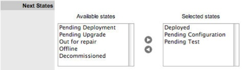
-
When all States have been allocated, click Save.
-
Save the assignment, and complete the process for all stages of the Item Lifecycle.
-
Customise settings if editing a Service CategoryAssign a Group within the associated Service Portfolio Team, this will allows these Users to edit the Item details when assigned this stage of the Category Lifecycle.
-
Click Save.
Move to the Classifications tab, to define request Classifications for the Item.
Deleting a State
It may be necessary to delete a system default State or a State that is no longer in use. Note that a State cannot be deleted if it has been assigned to an Item.
To delete an unused State:
-
Select .
-
Click on the hyperlink.
-
Move to the tab.
-
Select the link.
-
Click .
Create Category Classifications
A list of Classifications used to define issues are created within this tab and used as the generic Classification for requests logged against Items that apply the Item Type Category being configured. The Classifications are also used by the system for proactive Incident analysis and Problem groups.
Supervisor Users can define additional Classifications for specific Item Types, within the tab.
The system is installed with several default Classification Type Categories, which can be edited if required.
The General Classification is owned and used by the system and cannot be deleted. It is also advised that this Classification not be renamed, as this is the Classification assigned to requests when they are created via email.
Classification Tab
Additional Classifications can be created for each Item Category, while the system provided Classifications can be renamed or deleted. The Custom facility, when enabled, allows Users to add Classifications during the request creation process.
Creating a New Item Category Classification
To add a new Classification:
-
Within the Classification tab of an Item Category.
-
Highlight the Classifications header and click New.
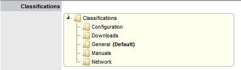
-
Enter the details in the newly created field.
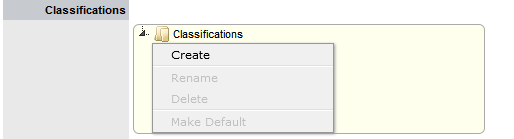
-
Click outside the text box to commit the entry listing.
-
To move an existing Classification to a new position, select the entry, then drag and drop the entry into its new location.
-
Click .
Creating Sub-Categories
Classifications can be expanded to include Sub-Categories.
To create Sub-Categories:
-
Select the relevant Classification header.
The Classification header is highlighted.
-
Click New.
A text box will appear under the Classification.

-
Enter the field details.
-
Click away from the text box to commit and save the change.
-
To move an existing Classification to a new position, select the entry, then drag and drop the entry into its new location.
-
The above steps can be repeated until the sub-category list is completed.
Renaming a Classification
Any Item Category Classification can be renamed.
To rename a Classification:
-
Select the .

-
Click .
-
Edit the field content.
-
Click away from the text field to save the change.
Deleting a Classification
To delete a Classification:
-
Highlight a relevant list entry.
-
Click .
-
When the Classification Categories are complete, click .
Creating Service Type Templates and Service Items
For service organizations wanting to fast-track the capability to manage requests in the system, it is advised to create Service Items in the Service Catalog to allow Customers and Technicians to log and manage requests within the application. Create a Type using the Service Category for each Service being offered, then create the Service Item with the newly created Type template. For the Service to be available in the Catalog, be sure the Service Item status is set to an Active, non Pre-production State. If the Customers are to access a Service on the Customer Portal, the Service Item Lifecycle State should also be set to Customer Visible.
Creating Item Types
If the Types are not to be automatically created as part of an AMIE or .csv import, this is done in the tab. This is where the Category template is associated with the Type template, the default Teams and SLA are set, and the Classifications for issues reported against Items are refined.
If Items are to be imported via a .csv file or AMIE proceed to the next step.
Item Types are templates used to create Items. Items are specific instances of Item Types with individual asset detail information.
For Item Types that use a Category with the Service Category functionality enabled, a Costs tab is also displayed that allows a User with the Finance Role to forecast the costs for offering the Service Item that applies the Item Type.
Creating a New Item Type
-
Select .
-
Click .
The screen appears.
-
Enter the Name of the Item Type.
-
Enter a Manufacturer using the drop-down list, or Select
to add a Manufacturer.The Manufacturer screen appears.
-
Name: Name of the Item Type.
-
Manufacturer: The manufacturer of the Item Type. New manufacturers can be created and existing manufacturers can be edited and deleted by using the Edit and New buttons that appear beside the drop-down menu of manufacturers.
-
-
Using the drop-down list, select the relevant Item Category.
-
Select the Criticality for the Item Type.
-
Item Category: This signifies the type of Item. (Hardware, Software or Service are the default Types, but Users with the Supervisor Role can create more if required).
-
Identifier: The drop-down list that appears is drawn from the fields defined for the Item Category selected. Although this information is not required, the Identifier is used to differentiate similar Items that may be in use throughout an organization. For example, if an organization uses the same printers for all departments, an Item Category field of "Location" could be configured for the Item Details and this could also be used as a secondary Identifier for Printer Item.
-
Criticality: Rates the degree of importance of an Item Type within an organization, which can be adjusted on a per Item basis. The 'Impact' of a Request is initially pulled from the Criticality of the Item, but can be adjusted within the request Information screen if required. Requests logged through the Customer Portal, use the Criticality of the Item to set the Priority of the request.
The Incident Analyzer, if enabled by the Administrator in , can apply the Criticality to automatically detect Problems.
The minimum Criticality level can also be used to determine the offline Items that appear on Outages pages, if the Outages pages are enabled by the Administrator in .
-
Icon: When the Type details are saved, the Icon selected for the Item Category will be displayed. To customize the icon for the specific Item Type, select the Icon to access the Upload inline_upload.png or Cancel inline_cancel.png options.
-
Unit Price: The per-unit price of the Item Type.
-
Instance Total: Number of instances owned by the organization.
-
Assigned: Number of instances assigned to Customers as Items.
-
Hidden: Select 'On' to ensure Customers cannot view this Item Type within the list in the Customer Portal. If all Item Types use this selection, the Item Type list will be completely removed from the Portal. Items created using Item Types with Hidden enabled, will not allow Customers to generate requests against them in the Customer Portal, nor will they be able to view or receive updates about requests logged by the User against Items with this functionality enabled.
-
Creation: Enabling this option gives Customers using the portal the ability to create new Items using this Item Type (if they have been granted the ability to create Items by the Administrator in . (This option is not displayed when the Hidden option is enabled.)
-
Ignore Share: Enabling this option overrides the system level option for sharing requests raised against Items of this Type. Requests raised against Items of this Type will not appear in the customer portal when viewing shared requests is enabled.
-
Add Forum Topic: Create a forum topic using the Item Type Name. This option is only displayed when a new Type is being created.
-
Incident Default: The Team of Technicians assigned to support Incidents received related to the Item Type.
-
Problem Default: The Team of Technicians assigned to support Problems received related to the Item Type.
-
Change Default: The Team of Technicians assigned to support Change Requests received related to the Item Type.
-
Request Default: The Team of Technicians assigned to support Service Requests received related to the Item Type.
-
Service Level Default: The default service level for the Item Type. When Billing is enabled, service levels without a cost are listed as an option. The service level with an associated cost can be applied when the Item created, this ensures Item contract payment is processed.
-
Support Levels: All Service Level Agreements assigned to the Item Type, which will be displayed as options when a request is created applying Item that uses this Type template. SLAs listed here, are used within the Costs tab of Service Types to forecast break even points on the Service relative to the number of Users.
-
Find SLA (Name): To assign multiple SLAs use this option. Click inline_search.png to view all SLAs or refine the search by entering a specific name. Select the SLA hyperlink to assign the SLA to the Type Information. Click inline_cancel.png to clear the search field.
-
-
Enter the Unit Price for the Item Type. This is an optional field that is used for asset management.
-
Set the Customer options.
-
Assign the default support Teams.
-
Assign one or multiple SLAs, as required.
-
Click Save.
-
Click the icon if the generic Item Category icon image is to be changed for the Item Type.
This icon is used as the visual representation of the Item Type in the Relationship Map.
The dimensions of the uploaded icon must be exactly 32x32 or 64x64 pixels.
-
Move to the Classification tab to create problem classification for this Item Type.
Click on the Item Type name to continue configuration.
SLAs and Item Types
When an Item Type is created with a defined SLA, any Item created using this Item Type automatically inherits the SLA. The lifecycle of a request raised against this Item is determined by the SLA triggers. However, it should be noted that the SLA can be adjusted within the Item if it is relevant to do so.
Classification
Category Classifications are used as generic problem classification for sorting requests. These are refined within the Item Type Classification to make them more relevant to the actual Item Type. For example, the Item Type category Hardware needs the Category Classification to be refined differently for hardware Item Types such as desktops and servers. To refine the problem types, Item Type Classifications are used.
Editing an Item Type Classification Listing
-
Within the tab.
-
Select .
A button is displayed within the section.
-
Click .
A New Entry field is displayed.
-
Complete the details of the new field.
-
Click outside the text field to save the entry.
-
To re-name an entry, highlight the field.
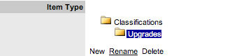
-
Select the Rename option.
The field opens in edit mode.
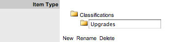
-
Change the details.
-
Click outside the text field to save the changes.
-
Move existing Classifications to a new position, if required Highlight the entry, then drag and drop the entry into its new location.
-
Click .
Creating Sub-Categories
Classifications can be expanded to include sub-categories.
-
Select the relevant Classification header.
The Classification header is highlighted.
-
Click New.
A New Entry field is displayed.
-
Complete the details of the New Entry field.
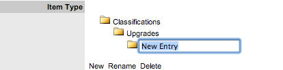
-
Click away from the text field to save the change.
-
The above steps can be repeated until the Sub-Category list is completed.
Items
The Items tab lists the Items created using this Item Type. Individual Item details can be viewed by clicking on an Item Number. The list of Items can be exported using the Excel button.
Requests
The Requests tab lists all requests that have been created for this Item Type.
Use the Filter to switch between Incident, Problem, Change and Service Requests views. Requests can be viewed from this screen by clicking on the Task# or Problem Report hyperlink. The list of Requests can be exported using the Excel button.
Costs
This is only visible to Users with the Finance Role.
The Costs tab is only available within the Service Type Information screens and allows organizations to calculate the Break-Even Point (BEP) of a service based on forecasting the number of Customers of that Service. This allows the service organization to account for the per calendar month price of the Service, which is used to calculate the ongoing revenue figures within the Item Costs tab that uses the Service Type template.
-
Capital: Enter the sum total to be invested in hardware and software infrastructure that will underpin the Service.
-
Recovery: Complete the field with the expected number of years designated to recover the costs of implementing the Service.
-
Recurring (Forecast Costs): Enter the proposed ongoing cost, on a per calendar month basis, for offering the Service.
-
Services: Using the details entered in the Costs fields and the cost per annum of the SLA, enter the forecast number of Customers/Users to calculate the break even point (B.E.P) of the Service. Using the auto-calculated B.E.P., enter a per calendar month Price for the Service to recover costs. This figure is used in the Service Item Costs tab to calculate the ongoing Revenue figures.
If an SLA with an Internal Cost is assigned to the Type, the B.E.P will be the SLA cost divided by 12 plus the cost of recovering the Capital expenditure over the number of years defined for the Capital to be recovered. For example, where the SLA cost is $240 for the year, the B.E.P will never be less than $20 per month.
-
Capital: Content for this field is derived from the Cost field within then Costs tab of the Item created using this Type.
-
Recurring (Actual Costs): Content for this field is derived from the Monthly Cost field within the Costs tab of the Item created using this Type.
Fields
Within the system, service organizations can refine custom fields made available during the request creation process based on the Item assigned to the request. In the Fields tab a User can create custom fields that apply to the Item Type. Therefore, when a request is logged against an Item that uses an Item Type with custom fields configured within the Fields tab, the Fields are made available within the Details tab of the request creation process.
These fields are in addition to the fields created by the Administrator within the , which are created for the specific Process, such as Incident, Problem, Change and Service Requests.
To create Field labels within the Type Information screen:
-
Click the tab.
-
Click .
-
Select a hyperlink.
The Custom Field screen is displayed.
-
Click Yes to activate the Field.
-
Complete the following details:
-
Field Label: The name of the field.
-
Active: Indicates if the field is active.
-
Required: Indicates if the field is required or mandatory field.
-
Customer Visible: Defines if the Customer can see the field within the Customer Portal. If Yes is selected, define if the Customer can edit the field information on the Customer Portal.
-
Data Type: Dictates the field's Data Type.
The options available include:
-
String - List or Free Text
-
Number
-
Boolean - radio buttons for Yes/No and True/False
-
Date - creates a date field
-
Currency- creates a currency field
-
Hyperlink
-
-
Style: States the style of the field. eg. String- List or Free Text field. See Lists for more information on creating a list field type.
-
Unique Value: When active, the system prevents the duplication of data within the customized field.
-
Default Value: Value entered is the default system entry for the field, when the field is not completed manually.
-
Input Validation: When enabled the Input Mask and User Mask can be defined. Input Mask : A regular expression to use for data validation of values entered by a User (i.e., Zip/Post Code, telephone no.) User Mask: A User Friendly representation of the Input Mask that Customers can understand should it appear in a validation error message.
-
Enable Description: When enabled a Description field appears, allowing the User to enter details of what information is the field is expected to capture. These details are accessible next to the custom field on the relevant screen.
-
-
Click Save.
The active Field will now be available during the request creation process, for all Items that use the Item Type.
Responses
The Responses tab within an Item Type displays the templates configured within the tab, which can be used as content for Notes sent for requests received against the Item Category. In addition to saving time for customer responses that are sent on a regular basis, these ensure the service desk responds to issues in a consistent manner, in line with the support organization's policies and protocol. Within the Types> Responses tab, additional Note templates can be configured, that will only be available for requests logged against that Item Type.
The following screen displays a list of default template options available within the Notes tab of a request:
Adding a Template for Item Types
-
Go to the tab.
-
Click .
-
Click .
-
Enter the Template Title.
-
Complete the content for the Note, inserting any relevant parameters.
-
Click .
Removing a Template
Within the > tab, only templates created for the Item Type can be deleted. Templates created at the Category level must be deleted within the tab.
-
Go to the tab.
-
Click .
-
Check the box in the column next to the Template Title.
-
Click .
-
Click .
Completing the Item Import
After the Items are successfully imported, a Supervisor User will need to refine the Type templates created as part of the import, if the default settings do not apply to a newly created Item Type. This task does not need to be completed immediately, and can be done on an ad hoc basis (i.e., whenever a Type template is opened in Edit mode, before saving, the system will prompt the User to set any required information.)
AMIE Import – Managing Items through Database Management
Within the CMDB Import screen multiple asset management datasources can be synchronized with the service management system. When one or more applications are configured within AMIE, a list is displayed within the CMDB Import tab.
Importing Items through Database Mapping
To import Items using Database Mapping, the following configuration steps need to be completed:
-
Select .
-
Click .
-
From the System Type drop-down list, select Database Mapping (AMIE).
The Server, Database and Synchronization fields appear.
-
System Type: Define the system type as Database Mapping.
-
Identifier: An identifying label that is used in List Views to inform Users regarding the Source of an Item.
-
Type (Server): Select the Type of inventory management product.
-
Type (Database): Select the Database Type.
-
Host: Enter the Host name or IP Address.
-
Port: Enter the Port Number for the database server.
-
Name: Enter the Database name.
-
Username: Complete User name details.
-
Password: Complete Password details.
-
Schema: Enter the Schema type.
-
Catalog: Enter the Catalog name. Typically this would be the name of the Database.
-
Email RFC's to Tech?: Select this option if technicians are to be notified of generated change requests.
-
Unassigned (Import Items as Global): Select this option if Items are to be globally owned.
-
System User: Select this option to assign imported Items to the System User.
-
Selected Customer: Select this option to assign imported Items to a specific Customer.
-
Auto Create New Items: This option is only visible when a single AMIE source is defined within AMIE. When enabled, Items are automatically created upon synchronization, relative to the Control CMS via RFC setting within the tab.
If disabled, a snapshot of imported asset information is listed within the tab.
-
Frequency: Choose a synchronization interval. This can be left as Never if the database will be synchronized manually.
Synchronization times will vary depending on the connection speed with the external service and the database size.
-
-
Click Test, to initiate a connection and test the setup If a connection is not made, a system message will advise which part of the configuration was not successful.
-
Click Save.
-
To execute the import, click the Import button.
-
After the import is complete, an Alert appears providing results of the import.
AMIE Import Alert
Alerts are generated for the Admin User after the AMIE synch is completed. The import alert summary displays:
-
The details of the system that the synchronization was run against, as it is possible to import from multiple sources.
-
The number of assets found in the datasource.
-
The number of assets automatically created if a single datasource is configured in AMIE and the auto-create option is enabled; or if the Auto-Create option is disabled and Items already exists in the system, the number of Items that were updated.
-
The number of AMIE Snapshots successfully imported, with a breakdown of new Items added and number of Items updated.
Delete Options and AMIE
The options to delete AMIE configurations can be achieved through the List View on the CMDB Import tab, or by clicking on the a hyperlink within the Server column within the List View, which displays the expanded Setup view for the specific asset management tool.
The Delete button clicked in the results in Global level "delete" flags being applied to all AMIE-managed Items stored in the system, however it retains the server details configured in AMIE and their associated snapshots.
The imported Items that are deleted are not completely removed from the database but are flagged as not available. By not erasing the Items completely, the historical data is maintained and allows these Items to be re-enabled in the future. It should be noted that the Item Types associated with the deleted imported Items are not disabled in the application.
The Delete button selected within the expanded Setup tab view for the specific asset management data source, results in Configuration level deletion of the configured server and any related AMIE snapshots.
The application must be restarted after the performance of either deletion operation, to allow the changes to take effect and prevent unpredictable behavior of the system.

To delete the server configuration within AMIE and related snapshots:
-
Select Setup > CMDB Import.
-
Select the Server option within the CMDB Import list view The expanded Setup screen is displayed with the Delete button.
-
Select the Delete button.
A pop-up message is displayed asking your to confirm the deletion request.
-
Click OK.
A warning message is displayed informing you to restart the application server to complete the deletion process.
Re-enabling Deleted Items
To re-enable Deleted Items, initiate an Item search on deleted Items within the Configuration>Items screen of the Supervisor view.
Within the Supervisor view to search for a deleted Item:
-
Select .
-
Click the Search button.
A simple search page will be displayed.
-
Enter a search term.
-
Select the option.
-
Click Search.
A list of Items is displayed.
-
For the Item to be re-enabled, select the Item ID#.
-
Click .
CSV Import – Importing Items by Using a .CSV File
To import Items using a .CSV file, a .CSV template, containing all available fields, can be downloaded and populated. The service management system uses a field mapping Wizard to match fields in the template to those in the system. To download the template go to Setup > Item Import > Import.
Before Importing a CSV File
For an Item to be successfully imported, the following fields must be mapped:
-
Support Team/s
-
Status
The Teams within the .CSV file must be created in the system before they can be associated with an Item as part of a .CSV import. Teams are created by a Supervisor under the tab.
Items are imported based on Category (i.e. Hardware, Software, etc.), which must be configured by the Supervisor within the Configuration> Categories tab before conducting a .CSV import. The Categories configuration define the Details recorded in the Item to be imported into the system. The Administrator must create separate .CSV files based on the Categories configured, that are then individually uploaded into the application.
For Items imported with owners, the Username in the .CSV file must match the Username within the support system. If the owner does not exist in the system, the imported Item will become a Global Item.
If relationships are to be created between Items upon import, Parent Items should be imported first. If the system generated Item Number is to be used for the Parent Item, it needs to be included in the Parent Item Number field of the Related Items when they are imported.
Importing Items
-
Select .
-
Select the tab.
To view a template that illustrates the fields the application is looking for and the data types (see below), click the Download Template link on the Item Import Wizard screen within Import tab of Item Import in the Setup tab.
The following fields should be visible:
Item Number(Unique char 64),Item Type(char 128),Manufacturer(char128),Incident Team(char 64),Problem Team(char 64),Change Team(char 64),Request Team(char 64), Company(char 128),Department(char 128),Room(char 64),Username (char 64),Status(char128),Criticality(char 64)Purchase Date(datetime),Cost(decimal),Field1(char 256),Field2(char 256),Field3(char 256),Field4(char 256),Field5(char 256),Field6(char 256),Field7(char 256),Field8(char 256),Field9(char 256), Field10(char 256),Field11(char 256),Field12(char256),Field13(char 256),Field14(char 256),Field15(char 256),Field16(char 256),Field17(char 256),Field18(char 256),Field19(char256),Field20(char 256),Notes(CLOB),Relationship Name(char256),Parent Item Number(char 64)
The char ### designation in parentheses after each field name signifies what type of data the import utility expects to see in each field. For instance:
Item Type (char 128) means that the first name field cannot exceed 128 characters.Fields marked as Unique must be unique in the system.
Note the Room details MUST be in the following format: COMPANYDEPARTMENT; Room
When creating a .CSV file for a Category, to determine the Field number of a configured Custom Field, within the Category tab of an Item Category select the System defined Ordering option. The field labels will then be listed in sequential order from one to twenty.
-
To import, select the Item Category.
The drop-down list consists of all Categories created by the Supervisor in .
-
Enter the file location, or use the button.
-
Select .
The Field Mapping Wizard appears. Fields that can be mapped to the CSV file are available in the drop-down list.
-
Use the drop-down list to select the fields to be mapped.
-
Map all necessary fields with those within the .CSV
-
Item Number: Unique Item number of the Configuration Item, this can be generated by the system or defined in the .CSV file.
-
Username: Customer owning the Configuration Item, imported by entering their user name.
-
Item Type II: Item Type of the Configuration Item.
-
Manufacturer I: Sets the manufacturer details of the Item.
-
Incident Team I: Incident Team assigned to the Configuration Item.
-
Problem Team I: Problem Team assigned to the Configuration Item.
-
Change Team I: Change Team assigned to the Configuration Item.
-
Request Team I: Request Team assigned to the Configuration Item.
-
Company I: Company owning the Configuration Item.
-
Department I: Department owning the Configuration Item.
-
Room I: The location of the Item. The .csv file data format to import this information MUST be: COMPANY-DEPARTMENT;Room
-
Status I: Default Configuration Item status.
-
Criticality: Sets the default criticality (i.e, critical, high, moderate, low, very low) for the Item. Optional.
-
Purchase Date: Date the Item was purchased.
-
Cost: The cost of the Item.
-
Monthly Cost: Sets the monthly Service Cost on per month basis for the Item.
-
Notes: Free text to add notes to the Item. Optional.
-
Fields 1 to 20: Custom fields created for the Category are displayed and can be mapped to the Item based on information included in the .CSV file.
-
Relationship Name: Defines the description of the relationship between the Item set in the following field.
-
Parent Item Number: Identifies the Item with which an Item is related using the Item Number.
-
Ignore First Line: Option to ignore first row upon import.
-
Verbose Errors: Detailed description of any errors that occur during the import process.
If relationships are to be created between Items upon import, Parent Items should be imported first. If the system generated Item Number is to be used for the Parent Item, it needs to be included in the Parent Item Number field of the Related Items when they are imported.
-
-
Select the checkbox if the first line of the imported CSV file has field headings.
Leave the checkbox clear if the CSV file begins with usable data.
-
Click to record a detailed description of any errors that occur during the import.
Leaving the box unchecked will return a summarized error report.
-
Select to bring into the system the mapped field data screen displays the results of the import.
-
Select .
Configuring Items after the Import
During the Item Import, elements that do not exist in the database are created. These are the fields marked with a blue line within the Field Mapping Wizard:
-
Item Type
-
Warranty
-
Organizational Units
After an import, all Item Types that have been created will need to be further configured.
To complete Item Type configuration:
-
Log in as Supervisor.
-
Select .
-
In the screen, click on the newly created Item. The Type Information screen appears.
-
Select .
A Manufacturer must be selected for a new Item Type. A manufacturer can be added using the dropdown list or a new manufacturer created using the New button.
-
From the dropdown list, select the Item Category.
-
In Incident Default, select the default Incident Team for this Item Type.
-
In Problem Default select the default Problem Team.
-
Define the default Change Default Team.
-
Set the default Service Request Team.
-
If relevant, set the default Service Level.
-
Click Save.
A
The .CSV file import facility can also be used to assign more than one Company and Department to an Item, if required. To assign multiple companies within the Company column of the .CSV file, enter the company names separated by a semi-colon (;) If the Company or Companies do not exist in the system, or have been deleted, a new Company will be created.
When importing multiple Departments related to the multiple Companies, the Department related to the Company must be listed in the same order as the Companies and separated by a semi-colon. For example:
Company Field: comp1;comp2 Department Field: dept1:depart2 or ;dept2 or dept1; Any departments that do not exist in the database or have been deleted, will be created as a result of the .CSV import.
To assign rooms to one of the locations of this multiple Company/Department assignment, the full details of the Company and Department must be entered into the column followed by a semi-colon and the Room number. An example of the Room import format is:
Company Field:CompName1;CompName2 Department Field:Dept1;Dept2 Room Field: CompName1 - Dept1;Room1
Updating Item Information via .CSV
To easily update multiple Items that already exist within system, information can be imported using a .CSV file. For the update to be successful, the Item number in the .CSV file must match the Item number in the system.
Follow the above Importing Items procedure and ensure the Item Number field is mapped correctly. If an Item Number is not included in the .CSV file, a new Item will be created.
Creating Items
If Items are to be created directly within the system, this is completed in the Configuration>Items tab. An Item Type template is selected for the new Item, which applies all the default information set within the Categories and Types tabs, then ownership of the Item is assigned to the new Item. Ownership can be Everyone (i.e., a Global Item), one or more specific Customers or Organizational Units. The specific attributes of the Item are recorded in the Details tab, and any relationships with other Items in the system can be created within the Relationships tab, now or at some point in the future.
Configuration Items within the system are referred to as Items. Items have multiple connections with other elements throughout the application, these may include Customers, Organizational Units and Service Level Agreements. The table below outlines how Items interact with other system elements:
-
Customers: Each Item must be assigned to one or more Customers who are the Owners of the Item. This Customer may be Everyone, making the Item a Global Item. Only Item Owners are able to raise requests against an Item.
-
Service Level Agreements (SLAs): Service Level Agreements can be linked as follows:
-
Per Item
-
Per Customer
-
Per Request or
-
To an Organizational Unit.
-
-
Teams: Within Item Types, Default Teams are assigned to Items. When requests are raised for an Item, they will be assigned to the Default Team.
-
Technicians: Technicians can be associated with Skills based on Items, Item Types and Classifications. When a request is raised with the combination of Item Type and issue Classification, it is assigned to that Technician.
-
Outages: Where states in the Lifecycle of an Item Type are defined as Off-line, when an Item is in an Off-line state, it will appear in the Outages page.
An Item record consists of the following attributes:
-
Information Tab
-
Details Tab
-
Costs Tab
-
Requests Tab
-
Relationships Tab.
Options available within the Items screen, include:
-
New - Create an Item
-
Search - Search for an Item
-
Bulk - Allows the User to update the ownership of Items in a bulk lot.
Filter views that are available within the screen include:
-
All Items: All Items stored within the CMDB, regardless of the assigned Lifecycle State.
-
Hardware Catalog: All Items that use the Hardware Category Template stored within the CMDB, regardless of the assigned Lifecycle State.
-
Service Catalog: All Items that use the Service Category Template stored within the CMDB that are in an active Lifecycle State.
-
Service Pipeline: All Items that use the Service Category Template stored within the CMDB that are assigned a Pre-production Lifecycle State.
-
Service Portfolio: All Items that use the Service Category Template stored within the CMDB,regardless of the assigned Lifecycle State.
-
Software Catalog: All Items that use the Software Category Template stored within the CMDB, regardless of the assigned Lifecycle State.
Viewing an Item
Within the Item sub-menu option, Users can view a list of Items created within the system. To view the details of an Item, select the Item Number hyperlink and the Item Information screen is displayed. The Item Information screen includes tabs for the following information:
-
Attribute details
-
Relevant costs
-
Requests created against the Item
-
Relationships associated with the Item