11.3 Configuring a Location
The following instructions help you configure a location’s settings, including defining the network environment parameters that identify the location.
Be aware that changing the settings for a location that is shared among policies affects all of the policies. To see if other policies will be affected by the location setting changes, right-click the location name (in the Locations tree), then click .
-
If the policy’s tab is already displayed in the Management Console, skip to Step 2. Otherwise, open the policy:
-
Double-click the policy in the list.
-
Click the tab.
-
-
In the Locations tree, select the location whose settings you want to configure.
-
Configure the desired location settings by referring to the following sections:
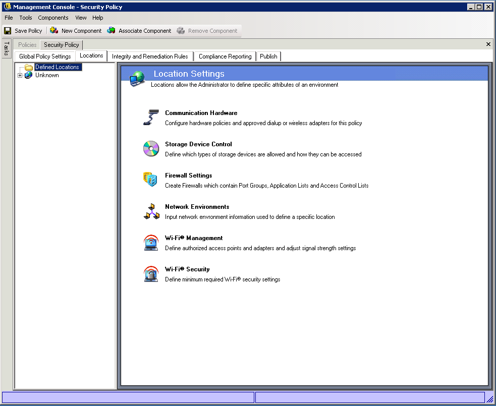
11.3.1 Locations
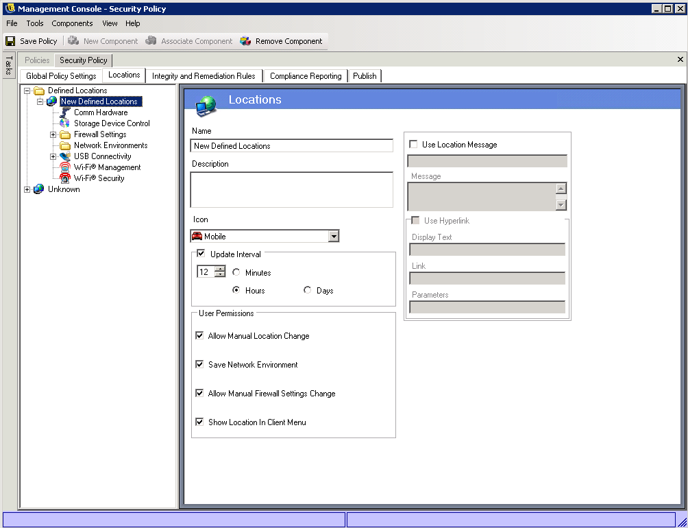
The Locations page lets you name the location, specify how often the Security Client checks for policy updates when associated with the location, and set user permissions for the location.
-
In the Locations tree of the Management Console, select the location.
-
Configure the settings as desired:
-
Name: Provide a unique name for the location. The name should be easily recognizable to Security Client users.
-
Description: Provide a description for the location.
-
Icon: The location icon provides a visual cue to the user which identifies their current location. The location icon displays on the taskbar in the notification area. Use the list to view and select from the available location icons.
-
Update Interval: This setting determines how often the Security Client checks for a policy update when it enters this location. The frequency time is set in minutes, hours, or days. Deselecting this parameter means the Security Client does not check for an update at this location.
-
User Permissions: The following settings determine what the user is allowed to do within the location:
-
Allow Manual Location Change: Permits the end user to change to and from this location. For non-managed locations (such as hot-spots, airports, and hotels), this permission should be granted. In controlled environments, where the network parameters are known, this permission can be disabled. The user cannot switch to or from any locations when this permission is disabled. Instead, the location the Security Client chooses (based on the network environment) is the one that is applied.
-
Save Network Environment: Allows the user to save the network environment to this location, to permit automatic switching to the location when the user returns. Recommended for any locations the user might need to switch to. Multiple network environments can be saved for a single location. For example, if a Location defined as Airport is part of the current policy, each airport visited by the user can be saved as a network environment for this location. This way, a mobile user can return to a saved airport environment, and the Security Client will automatically switch to the Airport location, and apply the defined security settings. A user may, of course, change to a location and not save the environment.
-
Allow Manual Firewall Settings Change: Allows a user to switch from one firewall setting to another.
-
Show Location in Client Menu: Displays the location in the Security Client menu. If this is not selected, the location is never displayed.
-
-
Use Location Message: Allows an optional Custom User Message to display when the Security Client switches to this location. This message can provide instructions for the end user, details about policy restrictions under this location, or include a hyperlink to more information.
-
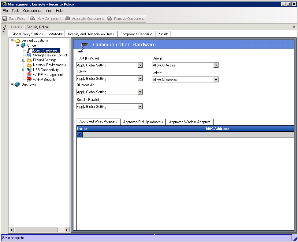
11.3.2 Communication Hardware
The Communication Hardware settings control which hardware types are permitted a connection at the location.
The Communication Hardware settings are also available as global policy settings (see Section 10.4, Communication Hardware). The location settings override the global settings and also provide some additional settings that are not available as global settings.
-
In the Locations tree of the Management Console, click the + sign next to the location to expand the location settings, then select .
-
For each communication hardware type listed below, select , , or :
-
1394 (FireWire): Controls the FireWire access port on the endpoint.
-
IrDA: Controls the infrared access port on the endpoint.
-
Bluetooth: Controls the Bluetooth access port on the endpoint.
-
Serial/Parallel: Controls serial and parallel port access on the endpoint.
-
Dialup: Controls modem connectivity for the location. If you want to limit access to specific modems, set this option to and then add the approved modems to the list.
-
Wired: Controls LAN card connectivity by location. If you want to limit access to specific wired adapters, set this option to and then add the approved adapters to the list.
-
-
(Optional) If you selected for the or settings and you want to limit the adapters that are allowed, add the approved adapters to the appropriate list ( or ).
Partial adapter names are permitted. Adapter names are limited to 50 characters and are case sensitive. Only the adapters included in the list are allowed; all other adapters are blocked.
-
(Optional) If you have enabled Wi-Fi (see Wi-Fi Management) and you want to limit the wireless adapters that are allowed, add the approved adapters to the list.
Partial adapter names are permitted. Adapter names are limited to 50 characters and are case sensitive. Only the adapters included in the list are allowed; all other adapters are blocked.
If the endpoint is in a location that defines only a Wi-Fi access point’s SSID as the network identification (see Wi-Fi Management), the Security Client switches to that location before disabling the unauthorized adapter. A password override should be used to provide a manual location switch if this occurs.
-
Click to save the changes.
The Security Client receives notification whenever a network device is installed in the system and determines if the device is approved. If it is not approved, the solution disables the device driver, which renders this new device unusable, and notifies the user.
When a new unapproved adapter first installs its drivers on the endpoint (via PCMCIA or USB), the adapter displays as Enabled in Windows Device Manager until the system is rebooted, but all network connectivity is blocked.
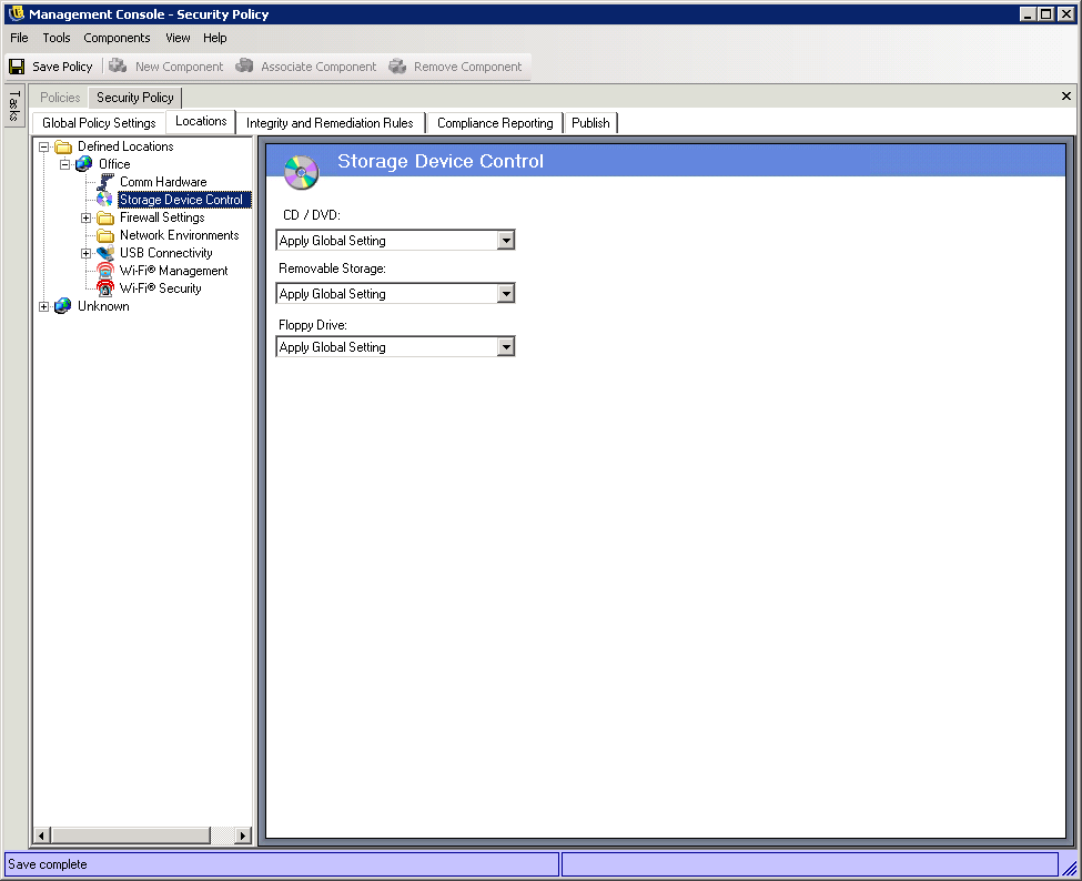
11.3.3 Storage Device Control
The Storage Device Control settings determine access to external storage devices (CD/DVDs, removable storage devices, and floppy drives). You can allow read/write access, read-only access, or no access. When a storage device is disabled (no access), users cannot to retrieve any data from the device; however, the hard drive and all network drives remain accessible and operational.
The Storage Device Control settings are also available as global policy settings (see Section 10.4, Communication Hardware). The location settings override the global settings. Some of the global settings, such as and , cannot be configured for a location; in this case, the global settings apply to the location.
-
In the Locations tree of the Management Console, click the + sign next to the location to expand the location settings, then select .
-
For , , and , select one of the following options:
-
Apply Global Setting: Use the global Storage Device Control setting.
-
Allow All Access: Read/write access is allowed.
-
Disable All Access: All access is prevented. When users attempt to access files on a defined storage device, they receive an error message from the operating system or the application attempting to access the local storage device, indicating that the action has failed
-
Read-Only Access: Read-only access is allowed. When users attempt to write to the device, they receive an error message from the operating system or the application attempting to access the local storage device, indicating that the action has failed
controls all devices listed under in Windows Device Manager. controls all devices listed under in Windows Device Manager. controls all devices listed under in Windows Device Manager.
To disable CD-ROM drives or floppy drives or to set them as read-only, the endpoint device’s Local Security Settings must have both and set as . By default, these settings are disabled. If you need to disable them or verify that they are disabled, open either the Active Directory group policy object or open on the target devices. Look in and verify that both settings are disabled.
-
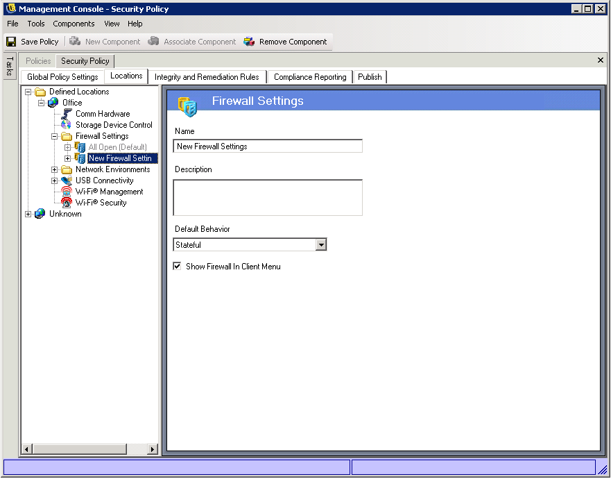
11.3.4 Firewall Settings
Each location is created with a default firewall setting. This default setting, named , opens all network ports (all network traffic is allowed), permits all packet types, and allows network access for all applications.
You cannot modify the firewall setting. If the location requires a more restrictive firewall setting, you can create a new firewall setting that provides the appropriate protection and designate the new firewall as the default firewall.
You can add multiple firewall settings if necessary. If you add more than one firewall setting, one is defined as the default setting, and the remaining settings are available as options for the user to switch to (if you have allowed firewall switching). Having multiple settings is useful when a user normally needs certain security restrictions within a location and might occasionally need those restrictions either lifted or increased for a short time or for specific types of networking such as ICMP Broadcasts.
To add a firewall setting:
-
In the Locations tree of the Management Console, click the + symbol next to the location to expand the location settings, then select .
-
If you want to define a new firewall setting, click on the Policy toolbar.
or
If you want to add an existing firewall setting, click on the Policy toolbar.
The firewall setting is added under the Firewall Settings folder in the Locations tree. If you add a new firewall setting, the name is displayed as New Firewall Settings. If you add an existing firewall setting, the setting’s name is displayed
-
On the Firewall Settings page, fill in the following fields:
-
Name: Specify a name for the firewall setting
-
Description: Specify a description.
-
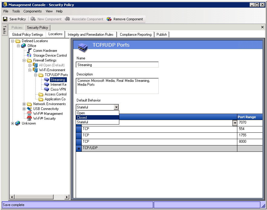
Default Behavior: Select the default behavior for the TCP/UDP ports:
-
Open: All network inbound and outbound traffic is allowed.
-
Closed: All inbound and outbound network traffic is blocked.
-
Stateful: All unsolicited inbound network traffic is blocked. All outbound network traffic is allowed.
Please note that the setting does not allow an active FTP session; you must use passive FTP instead. A good reference to explain active versus passive FTP is the Slacksite Web site.
You can use the TCP/UDP Ports page and the Access Control Lists page to override these default settings for specific ports and protocols.
For example, assume that the default behavior for all ports is set as All Stateful. The ports lists for Streaming Media and Web Browsing are added to the firewall setting. The Streaming Media port behavior is set as Closed, and the Web Browsing port behavior is set as Open. Network traffic through TCP Ports 7070, 554, 1755, and 8000 would be blocked. Network traffic through ports 80 and 443 would be open and visible on the network. All other ports would operate in Stateful mode, requiring the traffic through them be solicited first.
-
-
Show Firewall in Client Menu: Select this option to have the firewall displayed in the Security Client menu. This is necessary only if the user is allowed to switch firewalls for a location (see User Permissions).
-
-
If you want this firewall setting to be the default for this location, right-click the firewall setting in the Location tree, then click .
-
Click to save your changes.
-
Configure the desired firewall settings by referring to the following sections:.
TCP/UDP Ports
The TCP/UDP Ports setting allows you to create a TCP/UDP port group and assign a behavior (Open, Closed, or Stateful) to the group. The behavior overrides the default port behavior configured for the firewall setting (see Step 3).
Be aware that when enforcing the firewall settings, the Security Client does not allow incoming connections to dynamically assigned ports. If an application requires an incoming connection, the port must be static and included in a TCP/UDP port group that is assigned the Open behavior. If the incoming connection is from a known remote device, an Access Control List can be used.
To add a new TCP/UDP port group:
-
In the Locations tree of the Management Console, select the folder ( > location > > firewall > ).
-
If you want to define a new TCP/UDP port group, click on the Policy toolbar.
or
If you want to add an existing TCP/UDP port group, click on the Policy toolbar. For information about the predefined port groups that you can use, see Section A.0, Predefined TCP/UDP Port Groups.
The port group is added under the TCP/UDP Ports folder in the Locations tree. If you add a new port list, the name is displayed as New TCP/UDP Ports. If you add an existing port list, the port list’s name is displayed
-
On the TCP/UDP Ports page, fill in the following fields:
-
Name: Specify a name for the port group.
-
Description: Specify a description.
-
Default Behavior: Select the behavior to apply to the port group:
-
Open: All inbound and outbound network traffic is allowed.
-
Closed: All inbound and outbound network traffic is blocked.
-
Stateful - All unsolicited inbound network traffic is blocked. All outbound network traffic is allowed.
-
-
-
Add ports to the group:
-
Click the field to select the port type (, , , , or ).
-
In the field, specify a single port or a range of ports:
For example, 1-100 would add all ports between 1 and 100.
See the Internet Assigned Numbers Authority pages for a complete Ports and transport types list.
-
Repeat Step 4.a and Step 4.b to add additional ports to the group.
If you need to delete a port, select the port’s row, press the key on the keyboard, and click to confirm the deletion.
-
-
Click to save your changes.
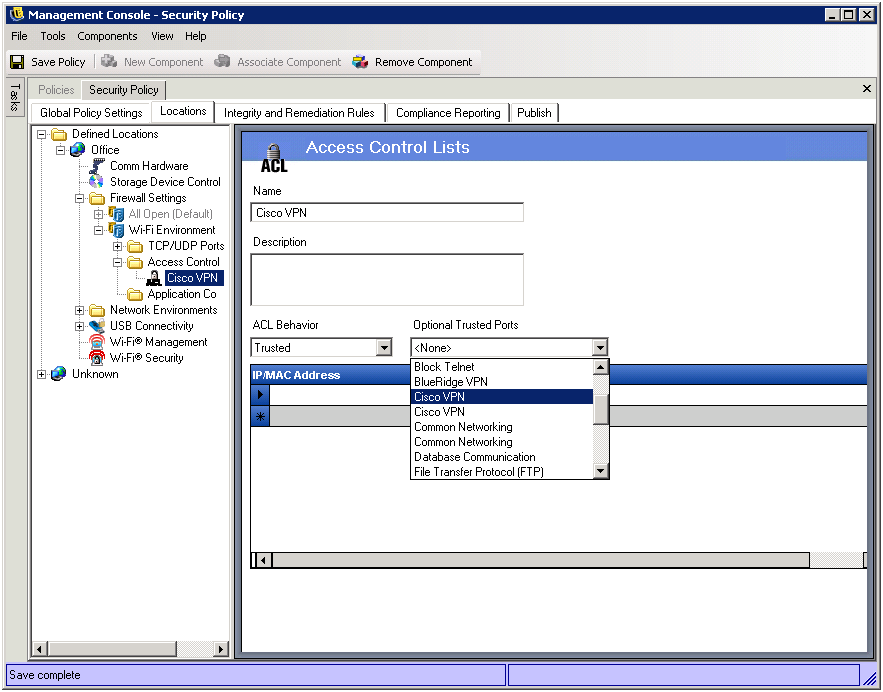
Access Control Lists
Some IP or MAC addresses might require unsolicited traffic to be passed regardless of the current port behavior (such as an enterprise back-up server or exchange server). In instances where unsolicited traffic needs to be passed to and from trusted servers, an Access Control List (ACL) can be created to provide this support.
To add an Access Control List:
-
In the Locations tree of the Management Console, select the Access Control Lists folder ( > location > > firewall > )
-
If you want to define a new list, click on the Policy toolbar.
or
If you want to add an existing list, click on the Policy toolbar. For information about the predefined lists that you can use, see Section B.0, Predefined Access Control Lists.
The Access Control List is added under the Access Control Lists folder in the Locations tree. If you add a new list, the name is displayed as New Access Control Lists. If you add an existing list, the list’s name is displayed
-
Name the ACL and provide a description.
-
Add addresses to the list. To do so:
-
In the IP/MAC Address field, specify the address:
-
IP: Specify a single standard IP address (example: 123.45.6.189) or a range of IP addresses (example: 123.0.0.0 - 123.0.0.255).
-
MAC: Specify a standard MAC address separated by colons (example: 00:01:02:34:05:B6).
-
ACL Macro: There are 16 predefined ACLs that you can add to the list. For information about using the ACLs, see Section B.0, Predefined Access Control Lists.
-
-
Click the Type field to select the address type ( or ).
-
Repeat Step 4.a and Step 4.b to add additional addresses to the list.
If you need to delete an address, select the row, press the key on the keyboard, and click to confirm the deletion.
-
-
In the list, select whether the ACL is (allow it always even if all TCP/UDP ports are closed) or (access is blocked).
-
If the ACL Behavior is , select the Optional Trusted Ports (TCP/UDP) for this ACL to use.
These ports permit all ACL traffic, while other TCP/UDP ports maintain their current settings. Selecting means any port may be used by this ACL.
-
Click to save your changes.
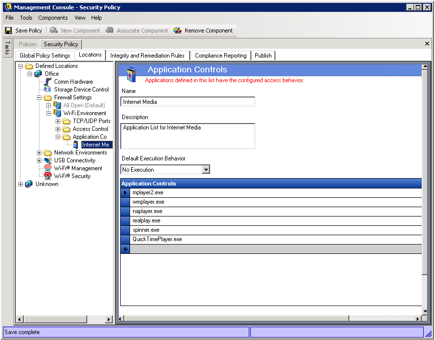
Application Controls
The setting lets you block applications either from executing or from gaining network access.
-
In the Locations tree of the Management Console, select the Application Controls folder ( > location > > firewall > )
-
If you want to define a new control, click on the Policy toolbar.
or
If you want to add an existing control, click on the Policy toolbar.
The Application Control is added under the Application Controls folder in the Locations tree. If you added a new list, the name is displayed as New Application Controls. If you added an existing control, the control’s name is displayed
-
Name the application control and provide a description.
-
Select an execution behavior.
This behavior is applied to all applications listed. If multiple behaviors are required (for example, some networking applications are denied network access, but all file sharing applications are denied execution), you need to define multiple application controls. Select one of the following:
-
No Execution: All applications listed are not permitted to execute.
-
No Internet Access: All applications listed are denied Internet access. Applications (such as Web browsers) launched from an application will also be denied access.
Be aware of the following:
-
Application Control does not function if the endpoint device is booted to Safe Mode with Networking.
-
Blocking execution of an application does not shut down the application if it is already open on the endpoint device.
-
Blocking execution of an application does not stop the application if it is started from a network share that has System blocked from read access.
-
Blocking Internet access for an application does not affect saving files to mapped network drives. Users are permitted to save to all network drives available to them.
-
Blocking Internet access for an application does not stop the application if it is already actively streaming network data to the endpoint device.
-
Blocking Internet access for an application does not stop the application from getting data from a network share.
-
-
Add applications to the list by using the following guidelines:
-
Add one application per row.
-
Specify only the executable name (no path).
-
If you need to delete an application, select the row, press the key on the keyboard, and click to confirm the deletion.
-
If the same application is added to two different Application Controls in the same firewall setting (for example, kazaa.exe is blocked from executing in one application control, and blocked from gaining network access in another defined application control under the same firewall setting), the most stringent control for the given executable will be applied (i.e., kazaa would be blocked from executing).
IMPORTANT:Blocking execution of critical applications could have an adverse affect on system operation. Blocked Microsoft Office applications will attempt to run their installation program.
-
-
Click to save your changes.
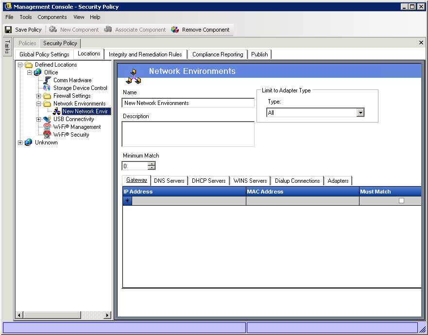
11.3.5 Network Environments
The settings let you specify the network services (Gateway servers, DNS servers, wireless access points, and so forth) that identify the location. You can specify which services are required and which are optional. For the device’s current environment to match the defined network environment and associate the device to the network environment’s location, required services must be present and optional services might or might not be present.
To define a network environment for the location:
-
In the Locations tree of the Management Console, select the Network Environments folder ( > location > ).
-
If you want to define a new network environment, click on the Policy toolbar.
or
If you want to add an existing network environment, click on the Policy toolbar.
The network environment is added under the Network Environments folder in the Locations tree. If you add a new network environment, the name is displayed as New Network Environments. If you add an existing network environment, the environment’s name is displayed.
-
Name the network environment and provide a description
-
If you want to limit when this network environment is available based on adapter type, use the field to select the allowed adapter type. The default () allows all adapter types.
-
For each service (, , , and ) you want to use to define the network, specify the following information to define the service:
-
IP Address: Limited to 15 characters. Use only the numbers 0-9 and periods (for example, 123.45.6.789)
-
MAC Address (Optional): Limited to 12 characters. Use only the numbers 0-9 and the letters A-F (uppercase and lowercase) separated by colons (for example, 00:01:02:34:05:B6). The list does not include this field.
-
Must Match: Select whether the presence of this service is required to identify the network environment
-
-
For s, specify the phone book entry:
The RAS Entry name from the phone book or the dialed number can be specified. Phone book entries can contain alphanumeric characters (a-z, 1-9) and special characters (@, #, $,%, -, etc.), but cannot contain only numeric characters and special characters. Entries that only contain special and numeric characters are assumed to be dialed numbers.
-
If you want to restrict the allowed adapters to specific adapters, use the list.
Adapters can be specified to restrict the allowed adapter types (see Step 4) to specific adapters. Enter the SSID for each allowed adapter. If no SSIDs are specified, all adapters of the permitted type are granted access
-
In the field, select the minimum number of network services that must match in order for this network environment to match the device’s current environment.
This number must be equal to or greater than the number of Must Match services you defined. For example, if you defined four Must Match services and ten optional services, you could specify 7 in the field. This would required all four Must Match services to be matched along with any three of the ten optional services.
-
Click to save your changes.
You can associate additional network environments to the location. If you have multiple locations in the same security policy, be aware that associating a single network environment to two or more locations within in the same security policy causes unpredictable results and is not recommended.
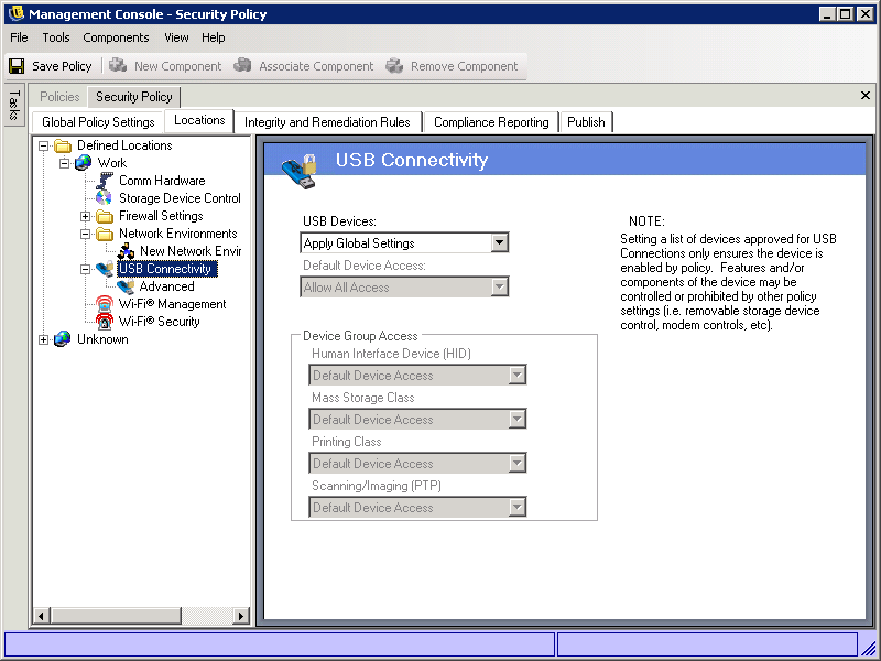
11.3.6 USB Connectivity
The USB Connectivity settings control access to devices that connect via the USB bus. The settings provide control at the following levels: all devices, device groups (classes), and individual devices. This gives you great flexibility in defining approved devices (whitelists) and prohibited devices (blacklists).
For example, assume that your organization supports only two authorized USB printers. You could allow access to all USB devices, block access to the printer device class, and then allow access to your two authorized printers. The result is a printer whitelist that includes only your two authorized printers.
The USB Connectivity settings are also available as global policy settings (see Section 10.6, USB Connectivity). The location settings override the global settings.
How the Access Setting Is Determined
To effectively use the USB Connectivity settings, you need to understand how the various settings are used to determine a device’s access.
When a device is detected, the first setting that is evaluated is the setting. If the setting is , the evaluation continues. If the setting is , the USB device is disabled and evaluation stops.
If the evaluation continues, the device’s attributes (Device Class, Manufacturer, Product, and so forth) are compared to the attributes associated with the device groups (in ) and individual devices (in the device list on the page). In some cases, the device might match more than one group and device. For example, a removable storage device might match both the Mass Storage Class group and an individually defined device.
In order to know which access setting to apply to a USB device, the Security Client builds an access filter against which to evaluate devices. If multiple security policies apply, the Security Client uses the USB Connectivity settings from all applied policies to build the access filter.
The filter includes each access setting (,, , , and ) and the device groups and devices assigned to the setting. For example, assume the following group and device assignments for each access setting:
A USB device is evaluated against the filter, beginning with the first setting () and continuing to the last (). If the device matches one of the device groups or devices assigned to the access setting, the device receives that access setting and the evaluation ends. If a device does not match any of the groups or devices, it receives the default device access.
Consider the following examples:
-
Mouse1(a Human Interface Device) is detected. It is evaluated against the first setting (). Because Mouse1 matches the Mouse1 device assignment for the setting, Mouse1 is blocked and no further evaluation is required.
-
Mouse4 (a Human Interface Device) is detected. It is evaluated against the setting. Mouse4 does not match any assignments (group or device), so it is evaluated against the assignments. Because Mouse4 is a Human Interface Device and that device group is assigned the setting, Mouse4 is allowed and no further evaluation is required.
-
Thumbdrive1 and Thumbdrive5 (two Mass Storage Class devices) are detected. Thumbdrive5 is blocked because its device assignment () precedes its Mass Storage Class group assignment (). Thumbdrive1 is allowed because it is included in the Mass Storage Class group assignment () and it does not match a device assignment.
-
Printer2 and Printer4 (two Printing Class devices) are detected. Printer4 is allowed because its device assignment () precedes its Printing Class group assignment (). Printer2 is blocked because its Printing Class group assignment precedes its device assignment ().
Configuring the USB Connectivity Settings
-
In the Locations tree of the Management Console, click the + sign next to the location to expand the location settings, then select
-
Configure the settings as desired:
-
USB Devices: Device access is first evaluated based on whether the USB bus is active or not. If this setting is set to , the device is disabled and evaluation stops. If this setting is set to , the Security Client continues the evaluation based on the remaining settings. Select if you want to use the policy’s global USB Connectivity settings.
-
Default Device Access: Select the default access ( or ) that will be assigned to USB devices in the following situations:
-
A USB device does not match one of the defined device groups or devices.
-
A USB device matches a defined device group or device whose access is set to .
-
-
Device Group Access: For each device group listed, select the access you want assigned to the group:
-
Always Block: Always block the device. This setting cannot be overridden.
-
Always Allow: Always allow access unless the device matches an filter.
-
Block: Block access unless the device matches an filter.
-
Allow: Allow access unless the device matches an or a filter.
-
Default Device Access: Give the device the same access level as if no other match is found.
The device groups are determined by the following classes. If a USB device’s class corresponds to one of the groups, it receives the group’s assigned access.
-
-
-
If you want to define individual devices, click the plus sign next to in the tree, then click . Otherwise, skip to Step 6.
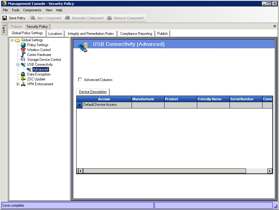
In most situations, the four device groups listed on the USB Connectivity page (Human Interface Device, Mass Storage Class, Printing Class, and Scanning/Imaging) are sufficient to allow or deny access to most USB devices. If you have devices that do not register in one of these groups, you can configure settings on the USB Connectivity Advanced page. You can also use the settings on the Advanced page to provide whitelist access to certain devices even though they might be denied access because of the settings on the USB Connectivity page.
-
To add a device to the list, fill in the device fields.
A device makes a set of attributes available to the OS. These attributes are matched by the Security Client to the fields required by a filter. All fields in the filter must match an attribute provided by the device in order to have a match. If the device does not provide an attribute or field that is required by the filter, that filter fails to match.
For example, suppose that a device provides the following attributes: Manufacturer: Acme, Class: 8, Serial Number: "1234".
The Class == 8 filter would match this device. The Product == "Acme" filter would not match because the device did not provide a Product attribute to the OS.
The , , and fields are substring matched. All other fields are exact matches.
-
Access: Select an access level:
-
Always Block: Always block the device. This setting cannot be overridden.
-
Always Allow: Always allow access unless the device matches an filter.
-
Block: Block access unless the device matches an filter.
-
Allow: Allow access unless the device matches an filter or a filter.
-
Default Device Access: Give the device the same access level as if no other match is found.
-
-
Manufacturer: Click the column, then type the name of the manufacturer (such as Canon). This is a substring match field, meaning that both C and Can would match Canon.
-
Product: Click the column, then type the name of the product. This is a substring match field, meaning that both C and Can would match Canon.
-
Friendly Name: Click the column, then type the friendly name of the device. This is a substring match field, meaning that both C and Can would match Canon.
-
Serial Number: Click the column, then type the serial number of the device. A serial number produces a unique match only when used with the , , , and fields. This is an exact match field.
-
Comment: Click the column, then type a comment. This field is not used to match devices, so it can include any text you want.
-
-
If you want to use additional attributes to define the device, click
This adds the following columns: , , and .
All fields are exact match fields. Current valid values for the USB version in decimal are 512 - USB 2.0, 272 - USB 1.1, 256 - USB 1.0.
-
Click to save your changes.
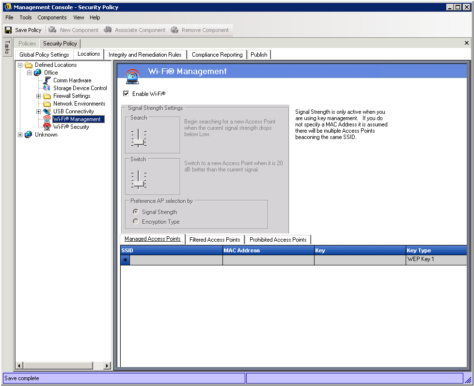
11.3.7 Wi-Fi Management
The Wi-Fi Management settings are available only if Wi-Fi transmissions are enabled in the global Wireless Control settings (see Section 10.3, Wireless Control).
The Wi-Fi Management settings let you do the following:
-
Enable or disable Wi-Fi transmissions for the location. If you disable transmissions, all other settings are also disabled.
-
Control connections to access points by creating , , and lists.
-
For managed access points, set up automatic switching based on access point signal strength and encryption type.
To configure the Wi-Fi Management settings:
-
In the Locations tree of the Management Console, click the + sign next to the location to expand the location settings, then select
-
Select to enable wireless transmissions in this location.
This setting enables or disables the endpoint device’s wireless adapters. It applies to all supported Security Client operating systems (Windows 2000, XP, Vista, and 7).
-
Add access points to the ,, and lists.
The access point lists apply only to Windows XP endpoint devices. The Security Client does not support access point lists on Windows 2000, Vista, or 7 endpoint devices.
The Security Client integrates with the Windows XP Wireless Zero Configuration service to control the access points. The endpoint device should not use any third-party wireless network managers when managing access points through the Security Client. In essence, the Security Client functions as the wireless network manager; using a third-party wireless network manager can interfere with the Security Client and cause unpredictable results.
If an endpoint device is using a third-party wireless network manager, you should either 1) uninstall the manager, 2) prevent the manager from starting (for example, through an application control in the Firewall settings), or 3) instruct the user to delete any preferred network lists from the manager and not use the manager.
-
Managed Access Points: A managed access point is one for which you automatically distribute and apply Wired Equivalent Privacy (WEP) keys without user intervention. This protects the integrity of the keys by not passing them in the clear.
Because of the inherent security vulnerabilities of Shared WEP Key Authentication, Novell supports Open WEP Key Authentication only.
Specify the following information for each managed access point you want to define
-
SSID: Specify the SSID number. The SSID number is case sensitive.
-
MAC Address: Specify the MAC address. This is recommended because SSIDs might be duplicated. If the MAC address is not specified, it is assumed that there are multiple access points beaconing the same SSID number.
-
Key: Specify the WEP key for the access point (either 10 or 26 hexadecimal characters).
-
Key Type: Specify the encryption key index by selecting the appropriate level from the drop-down list.
-
Beaconing: Select this option if the defined access point is currently broadcasting its SSID. Leave it deselected if this is a non-beaconing access point.
The Security Client attempts to first connect to each beaconing access point listed in the policy. If no beaconing access is located, the Security Client then attempts to connect to any non-beaconing access points (identified by SSID) listed in the policy.
When one or more access points are defined in the list, the Signal Strength switching for the Wi-Fi adapter can be set (see Step 4).
-
-
Filtered Access Points: Specify the access points that can be displayed in the Wireless Zero Configuration interface. This only affects the access points that are displayed to users. Users can still connect to a non-displayed access point by manually entering the information. To prevent a user from connecting to an access point, you must add it to the list.
Specify the following information for each access point:
-
SSID: Specify the SSID number. The SSID number is case sensitive.
-
MAC Address: Specify the MAC address. This is recommended because SSIDs might be duplicated. If the MAC address is not specified, it is assumed that there are multiple access points beaconing the same SSID number.
-
-
Prohibited Access Points: Access points in the list do not display in the Wireless Zero Configuration interface, nor can the endpoint device connect to them.
Specify the following information for each access point you want to prohibit:
-
SSID: Specify the SSID number. The SSID number is case sensitive.
-
MAC Address: Specify the MAC address. This is recommended because SSIDs might be duplicated. If the MAC address is not specified, it is assumed that there are multiple access points beaconing the same SSID number.
-
-
-
Configure the settings.
When more than one WEP-managed access point is defined in the list, the signal strength switching for the Wi-Fi adapter can be set. The signal strength thresholds can be adjusted by location to determine when the Security Client searches for, discards, and switches to another access point defined in the list.
The following settings can be adjusted above or below the current defaults:
-
Search: When this signal strength level is reached, the Security Client begins to search for a new access point to connect to. The default setting is Low [-70 dB].
-
Switch: In order for the Security Client to connect to a new access point, that access point must broadcast at the designated signal strength level above the current connection. The default setting is +20 dB.
The signal strength thresholds are determined by the amount of power (in dB) reported through the computer’s miniport driver. Because each Wi-Fi card and radio might treat the dB signals differently for their Received Signal Strength Indication (RSSI), the numbers vary from adapter to adapter.
The default numbers associated with the defined thresholds in the Management Console are generic for most Wi-Fi adapters. You should research your Wi-Fi adapter's RSSI values to supply an accurate level. The Novell values are:
These signal strength names match those used by the Microsoft Zero Configuration Service, but the thresholds might not match. Zero Config determines its values based on the Signal to Noise Ratio (SNR) and not solely on the dB value reported from RSSI. For example, if a Wi-Fi adapter receives a signal at -54 dB and has a noise level of -22 dB, the SNR reports as 32dB (-54 - -22=32), which on the Zero Configuration scale translates as Excellent signal strength. However, on the Novell scale, the -54 dB signal indicates a Very Good signal strength.
The end user never sees the Novell signal strength thresholds; this information is provided to show the difference between what the user might see through Zero Config and what is actually occurring in the Security Client.
Because both signal strength and encryption type (see Wi-Fi Security) are used to determine the order in which access points are attempted, you must select the preferred method. For example, if signal strength is the preference, the strongest signal is given preference when connecting. If WEP 64 is the encryption requirement and encryption is the preference, access points with the highest encryption strength are given preference over all others.
-
-
Click to save your changes.
11.3.8 Wi-Fi Security
The Wi-Fi Security settings are available only if Wi-Fi transmissions are enabled in the global Wireless Control settings (see Section 10.3, Wireless Control) and in the location’s Wi-Fi Management settings (see Section 11.3.7, Wi-Fi Management).
The Wi-Fi Security settings let you specify the minimum encryption that an access point must provide in order for the Security Client to allow a connection to the access point. Access points that do not meet the minimum security requirement are not displayed. If a user tries to manually define a connection to the access point, the connection is blocked.
For example, if you select WPA, any access points that provide less secure encryption (WEP 128, WEP 64, or no encryption) are blocked.
To configure the Wi-Fi Security settings:
-
In the Locations tree of the Management Console, click the + sign next to the location to expand the location settings, then select
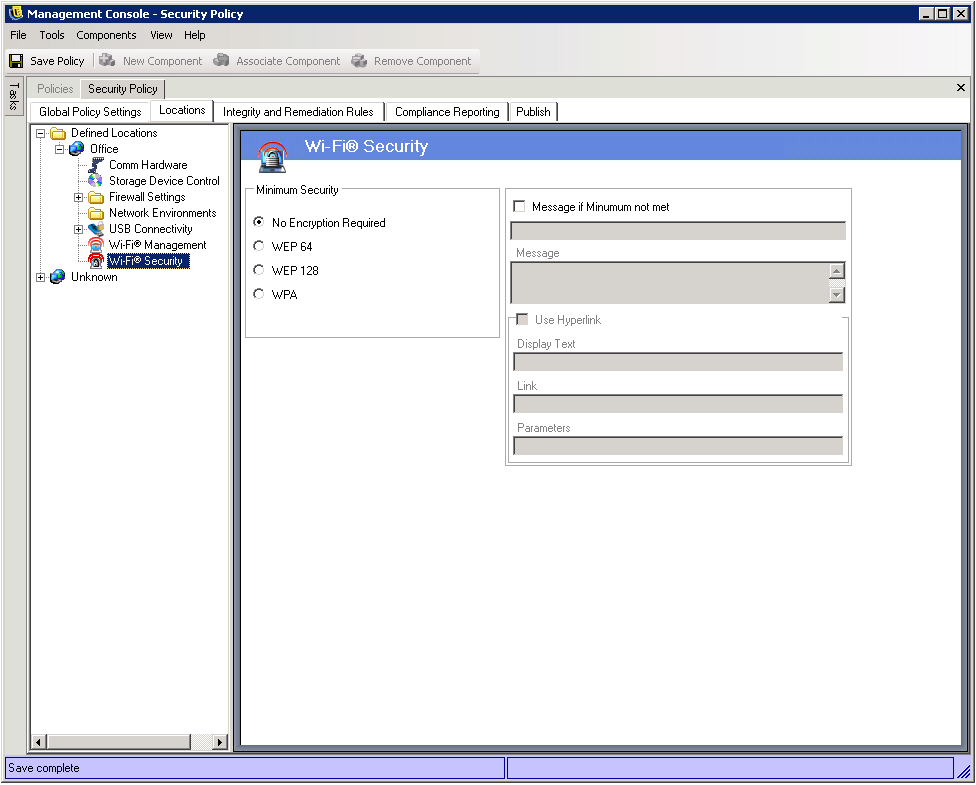
-
Select the level.
-
If you want to display a message to users when a connection fails because of insufficient security, select , then fill in the message fields.
-
Click to save your changes.