NetWare Link/X.25 Architecture
NetWare Link/X.25 implements the X.25 standard, which spans the bottom three layers in the OSI reference model for networking. Figure 2 represents the standard OSI layers and the corresponding X.25 layers.
Figure 2
OSI and X.25 layers
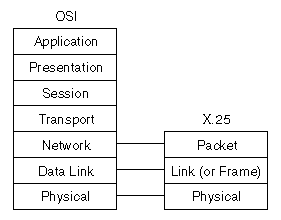
Table 1 lists the X.25 layers and provides their corresponding descriptions and protocols.
Table 1. X.25 Architecture
Packet |
Multiplexing (relay, routing, and switching) |
X.25 Packet Layer Protocol |
Link (or Frame) |
Point-to-point synchronization, error detection and correction, and flow control |
HDLC and LAPB |
Physical |
Bit transmission and media interface |
X.21 bis in the U.S. X.21 in Europe |
NetWare Link/X.25 consists of the following three layers:
- Packet---Corresponds to the Network layer in the OSI model. The most important feature of this layer is multiplexing. It controls call setup and clearing, packet transfer, and network facility selection. The Packet layer specifies the virtual circuit service for both switched virtual circuits (SVCs) and permanent virtual circuits (PVCs). It conforms to the ITU-T X.25 Packet-layer specification.
- Link---Transports data across the physical link, controls the interchange between the DTE and the DCE, and corrects any link errors. This is a subset of the ISO standard High-level Data Link Control (HDLC) protocol, known as Link Access Procedure-Balanced (LAPB). It conforms to the ITU-T X.25 Link-layer specification, except for the multilink procedure.
- Physical---Defines the physical interface between a DTE and DCE (the X.21 and X.21 bis specifications for physical attachment to the packet network). Recommendations include voltages, signaling, plug types, and pin connections.
For more information about NetWare Link/X.25 architecture, refer to NetWare Link/X.25 Components.

