29.4 Configuring Preboot Services Defaults
You can configure Preboot Services default settings for a ZENworks Management Zone. These are settings that apply globally to all devices in the management zone.
Some of these settings enable you to automatically register devices with the ZENworks Linux Management server, and some can be overridden by configurations done for devices or folders containing devices. For more information, see Section 29.5, Overriding Preboot Services Defaults.
The following default settings can be configured in the ZENworks Control Center:
29.4.1 Configuring Preboot Services Menu Options
To determine whether the Preboot Services Menu should be displayed on your devices when they boot:
-
In the ZENworks Control Center, click the tab, which displays the following section:
-
In this section, click to display the configuration sections.
-
-
Select one of the following:
IMPORTANT:Do not select if you have AutoYaST or kickstart bundles assigned to any devices, because the Preboot Services Menu interrupts the PXE boot process, keeping the AutoYaST or kickstart bundles from being deployed on the device. The Preboot Services Menu only has options for doing imaging work, not for installing operating systems.
Therefore, select either or for your Preboot Services Menu option, which allows PXE-enabled Linux devices to automatically implement the AutoYaST or kickstart bundles.
-
-
Click either or to save the change.
This sets the default Preboot Services Menu display mode for the ZENworks Management Zone. This can be overridden at the folder or device level. For more information, see Section 29.5, Overriding Preboot Services Defaults.
IMPORTANT:PXE must be enabled on the device for the menu to be displayed.
The Preboot Services menu provides options for how Preboot Services can be used on your devices. The following options are presented when the menu is displayed:
Table 29-6 Preboot Services Menu Options
Generally, if your Preboot Services work is completely automated, you should select to never display the Preboot Services Menu on the device when it boots. Conversely, if you need to do manual Preboot Services functions for some or all devices, then select to always display the menu. A compromise is where you select to display the menu if Ctrl+Alt is pressed, allowing unattended Preboot Services work while allowing you the opportunity to display the menu when needed.
29.4.2 Configuring Image Storage Security
To determine the degree of security you want with respect to saving image files:
-
In the ZENworks Control Center, click the tab, which displays the following section:
-
In this section, click to display the configuration sections.
-
Locate the section:
-
Select one or both of the following options:
Allow Preboot Services to overwrite existing files when uploading: Select this option only if you want existing image files to be overwritten during imaging.
Only allow uploads to the following directories: This option allows you to determine where images can be restored on the imaging server.
Specify a full path to the directory in the field, then click to enter it into the list box. These are the directories where images are allowed to be saved on the imaging server. These are the locations that can be selected when configuring where to store image files.
Use or to rearrange the order of the locations, including the order of the imaging servers that are listed.
To remove a directory path from the listing, select the path and click . You can select multiple paths for removing.
-
Click either or to save the changes.
This sets the default image storage settings for the ZENworks Management Zone.
29.4.3 Configuring Non-registered Device Settings
The following configurations can be set after a device is imaged. The settings are applied to devices not registered in the ZENworks Management Zone.
For more information, see Section 28.3.4, Non-registered Device Settings.
To configure default ID settings for non-registered devices:
-
In the ZENworks Control Center, click the tab, which displays the following section:
-
In this section, click to display the configuration sections.
-
Locate the section:
-
Fill in the fields:
DNS suffix: Provides a suffix for all of your device’s names.
For example, if you enter “provo.novell.com” and a device’s name is “device1,” that device’s full name becomes “device1.provo.novell.com.”
Name servers: To control what DNS servers the device uses, specify a DNS name server, then click to place it into the listing.
So that a booting device can find a name server efficiently, specify multiple DNS name servers.
For optimal availability of a DNS server for a device, you can rearrange the order using and , one name server entry at a time.
You can delete multiple name servers by selecting them and clicking .
Device name: You can determine the default device names for non-registered devices. The name is applied after the device is imaged.
This can be useful for when you have multiple devices to be imaged. You can automatically provide unique names for each device (from its BIOS asset tag or its BIOS serial number), as well as group devices by providing the same prefix for their names.
Options:
-
Use prefix: ____: This provides a common prefix to the device names, such as Lab1 to distinguish them from the devices in Lab2. This can be useful when doing bulk imaging of certain groups of devices. It is limited to 8 characters.
If this option is used, the prefix you enter here is appended with a random string of letters and numbers to make the device name 15 characters long. Underscores and hyphens are valid in your prefix. The remaining random string uniquely names the device.
For example, if you enter Lab1_, then ten other characters are randomly generated to complete the name with Lab1 separated from the random characters by the underscore for readability.
-
Use BIOS asset tag: This is the asset tag stored in the device’s BIOS, which is unique for every device. This can be useful for tracking a device based on its asset tag.
-
Use BIOS serial number: This is the serial number stored in the device’s BIOS, which is unique for every device. This can be useful for tracking a device based on its serial number.
-
Do not automatically assign a name: Select this option if you do not want to use any of the above options. This is the default option.
IP configuration: You can select either or to identify devices for Preboot Services work.
These are the settings that the device is told to use after it is imaged. It uses them for Preboot Services work any time it reboots.
-
Use DHCP: Allows the devices to be dynamically assigned IP addresses.
For Red Hat Enterprise Linux, using the DHCP option causes a “Could not look up Internet address...” message to be displayed during bootup. This is because zislnx does not know the IP address when DHCP is being used, so the /etc/hosts file contained in the image does not have the new IP address and host name. Simply select the option to continue. Then to prevent this message from displaying each time the device boots, edit the /etc/hosts file on the device and add in its IP address.
-
Specify address list: Uses IP addresses to identify your devices. The addresses you add to the list are available to be used by your devices. This way, you can specify a range of IP addresses or individual IP addresses that you want your devices to use. For example, you can ensure that all of your lab devices use addresses between 10.0.0.5 and 10.0.0.25.
If you select this option, the following fields are displayed:
Subnet mask: (Optional) For assigning devices to a specific subnet mask.
Default gateway: (Optional) For assigning devices to a specific gateway for access to the Internet or network after the device is imaged and rebooted.
IP addresses available for machines: According to the information you provide in this section, this list box displays the available IP addresses for your devices to use.
Start and end of IP address range: Do either of the following:
-
Specify one IP address at a time in the first field and click each time to place it into the list box.
-
Specify a range of IP addresses and click to place them into the list box. Each IP address in a range is listed independently, allowing you to selectively remove any of them from within the range.
You can select multiple IP addresses for removal.
IP addresses currently assigned: This display-only list box shows which IP addresses from the list have been assigned to a device. When they are displayed here, they are no longer displayed in the list box above.
After a device is imaged, IP settings are applied to the device. The IP address that is assigned to the imaged device is no longer in the available list, but is instead listed in this currently assigned list.
-
-
-
Click either or to save the changes.
This sets the default device ID method for the ZENworks Management Zone.
29.4.4 Configuring Preboot Work Assignments
This section allows you to set up Preboot work assignments for your defined bundles for non-registered devices, or registered devices that do not have an effective bundle defined.
In this section of the Preboot Services page, you can set up rules for your Preboot bundles. Work assignment rules are hardware keys used to determine which bundle should be applied to which device. When a device is seeking work to be done, it scans the rules until it finds a rule where all of the rule’s filters match the device, then executes the bundle assigned to the rule.
For more information, see Section 28.3.5, Preboot Work Assignment Rules.
To configure work assignment rules:
-
In the ZENworks Control Center, click the tab, which displays the following section:
-
In this section, click to display the configuration sections.
-
Locate the section:
-
If you plan to select when constructing a rule (see Step 12), you must first configure the hardware type in one of the following fields:
-
Servers: Specify a full or partial string that identifies a server’s BIOS from a match in its field, then click to place the string into the list. You can add multiple strings to the list in order to identify all of the servers that you want a rule to select. To remove a string from the list, select the string, then click .
-
Laptops: Specify a full or partial string that identifies a laptop’s BIOS from a match in its field, then click to place the string into the list. You can add multiple strings to the list in order to identify all of the laptops that you want a rule to select. To remove a string from the list, select the string, then click .
When defining a rule, you can define hardware types so that the rule can be specifically applied to either servers or laptops.
To determine the BIOS product names of your servers or laptops, use the img i command at a bash prompt, which displays various BIOS information. The BIOS information that you need is listed in the field. For servers and laptops, you can enter partial strings to select all with BIOS product names containing that string.
, , and are the three options available when defining a work assignment rule based on a hardware type. Devices whose BIOS identification matches one of the strings listed in the or fields above are classified for the rule as either a server or a laptop.
A workstation is a hardware type that does not require a BIOS string definition. Therefore, if you select or in the Rule Construction dialog, but you have not entered BIOS identification strings for them here, they are treated as workstations by the rule.
These hardware type definitions are applicable only to rules; they do not otherwise apply to the ZENworks Management Zone.
-
-
Click to configure a rule.
The information configured in the Rule Construction dialog box comprises one rule. You can add multiple rules. The rules are used to determined whether there is a device that should have any preboot work done. If so, it only does the effective preboot work assigned to it.
-
In the Rule Construction dialog box, provide a name for the work rule in the field.
This is the name that is displayed in the rules listing on the Preboot Services page in the section. Make it descriptive enough that you can later remember its purpose.
-
In the field, browse for or specify the bundle where you want to apply this rule.
Each rule can be applied to only one bundle. However, you can apply multiple rules to a bundle.
When a device boots and searches the section for work, if the device meets a rule’s criteria, the rule’s applicable bundle is applied to the device.
Because the rules, not the bundles, are listed in the section, you can apply multiple rules to a given bundle. In that case, such a bundle has multiple chances to be selected for preboot work.
When multiple rules are listed, the first rule to have criteria to match a device causes that rule’s assigned bundle to be applied to the device.
If no rules match a device, then the effective bundle is not applied to the device.
-
To determine which boot parameters to use, select one of the following for the field:
Use Kernel Boot Parameters from Zone’s Settings: Uses the ZENworks Management Zone’s settings as configured in the section.
Use These Kernel Boot Parameters: Specify the boot parameters to be used with one of the Preboot Services Menu options.
-
Review the following to understand how to configure the work rule logic:
A rule is made up of one or more filters that are used to determine whether a device complies with the rule. The Rule Construction dialog box begins with one empty filter. A device must match the entire filter list of a rule (as determined by the logical operators that are explained below) for the rule to apply to the device.
A filter is a row of fields providing a condition that must be met by a device in order for the bundle to be applied. For example, you can add a filter to specify that the device must have exactly 512 MB of RAM in order to be accepted by the rule, and you can add another filter to specify that the hard drive be at least 20 GB in size. There is no technical limit to the number of filters that you can add in the rule, but there are practical limits, such as:
-
Designing a rule that is easy to understand
-
Devising the rule so that you do not accidentally create conflicting filters
-
Being able to view the dialog box as it grows in size because of the filters that you add
Filters can be added individually or in sets. Each set contains logical operators within the set. The logical operator OR is displayed by default for the filters within a set in the field, which you can change, and AND is displayed in the field, which is display-only. In other words, the logical operator that is used within a set must be opposite the operator that is used between the sets.
You can think of filters and filter sets using algebraic notation parentheticals, where filters are contained within parentheses, and sets are separated into a series of parenthetical groups. Logical operators (AND and OR) separate the filters within a the parentheses, and the operators are used to separate the parentheticals.
For example, “(u AND v AND w) OR (x AND y AND z)” means “match either uvw or xyz.” In the Rule Construction dialog box, this looks like:
u AND v AND w OR x AND y AND z
Filter sets cannot be nested. You can only enter them in series, and the first filter set to match the device is used to validate using the applied bundle to do preboot work on the device. Therefore, the order they are listed does not matter. You are simply looking for a match to cause the bundle to be applied to the device.
HINT:You can easily run a test to see how these logical operators work. Access the Rule Construction dialog box, click both the and options a few times each to create a few filter sets, then switch between AND and OR in the field and observe how the operators change. Click to exit the Rule Construction dialog box when you are finished.
You can set up the conditions for a rule by adding all of the filters and filter sets that you need to identify the type of device you want to match. You typically do not need to set up complex rules. However, because you can apply multiple rules to a bundle, you can further complicate the use of logical operators, because each rule is considered to be an OR condition for the bundle, causing the bundle to be applied if any one of the rules matches the device. Therefore, keep in mind the OR condition of multiple rules for a bundle when designing your rules.
For example, you could create several rules for the bundle with each rule being a long listing of AND conditions to be met. Therefore, each rule becomes a specific set of criteria for a device to meet, causing the bundle to be applied if one is met. Conversely, if you have that same amount of information in one rule (using filter sets for the AND and OR conditions), it might make the dialog box so long that it becomes unmanageable.
To determine whether you need one filter set with multiple filters, multiple filter sets with only one or a few filters per set, multiple filter sets each with multiple filters, or even multiple rules per bundle, remember that the logical operators for filters within a set are the opposite of the operators between the sets, and all rules for a bundle use the OR condition.
For example, when selecting the operator in the field:
Obviously, adding filter sets complicates the use of logical operators, and adding multiple rules to the bundle further complicates it. Therefore, carefully plan how to place your information before using this dialog box.
-
-
To add or remove filters and filter sets, select from the following:
-
Add filter: Adds one filter (a row of fields) after the last filter in this dialog box.
Subsequent clicks of the option add those filters to the end of the current set, which is the last listed filter set when there are multiple filters in the set (see Add Filter Set below). You cannot insert a new filter between existing filters.
The order of the filters in a set does not matter, and you cannot reorder the filters after you have created them. What matters in this structure is properly grouping the filters with respect to the selected and operator options.
-
Add filter set: Adds the next filter as a filter set with either AND or OR placed between the filter sets, as dictated by your selection in the field.
To create filter sets, first click , then click as many times as necessary to add filters into that set.
You cannot insert filter sets between existing filter sets.
-
-
To determine the filter and filter set logic, select or from the drop-down list.
The logical operator you select here determines which operator is used within the filter sets. The operator for this field applies to multiple sets.
To provide multiple sets for the rule, indicate whether the sets should all be required (select ) or are all optional (keep ). If OR, then the values in only one of the sets need to match the device for the rule to apply. If AND, then all values in the entire rule must match the device for the rule to apply.
If you only have one filter set (which could contain several filters), AND is the default logical operator within the set, because OR defaults in the field, which you can change.
is a display-only field. When providing multiple sets for the rule, this field displays the opposite logical operator from the one you select for the field.
To require all filters within a filter set, but only one of the filter sets, select in the field. To require all filter sets, but only one of the filters within each set, select in the field.
-
To configure rule filters, fill in the fields:
-
Check box: Selects filters for deletion.
-
Drop-down list: If blank, this field means to do as worded in the filter. If you select , it means to do the opposite of what the filter says.
For example, if you select and the RAM size is configured to be “less than 512 MB,” then the device must have at least 512 MB of RAM for the bundle to be applied. In other words, the filter reads “not less than 512 MB of Ram.” Conversely, if you configured it as “more than 512 MB,” then left the field blank, any computer containing exactly 512 MB of RAM is excluded, which you might not intend. So, be sure that you think the logic through for your filter configurations with respect to whether you use NOT.
-
Device component: A drop-down list provides the various items available for matching on the device in order to determine whether the work rule applies for the bundle. The options are:
- BIOS Asset Tag
- BIOS Serial Number
- BIOS Version
- CPU Chipset
- Hard Disk Controller
- Hard Drive Size (in MB)
- Hardware Type
- IP Address
- MAC Address
- Model
- Network Adapter
- RAM (in MB)
- Sound Card
- System Manufacturer
- Video Adapter
If the drop-down list on the left displays NOT, then the work rule is stating that the device should not match the component as described in the next two fields.
To use the option effectively, you must first configure the settings for either the or field in the section in the work assignment configuration. The hardware type is the default and requires no configuration for it to be used. In other words, if you do not provide a BIOS identification string for a server or laptop, then select or in the field, the devices are treated as workstations, where a BIOS identification is not used.
-
Relationship to: This defines the relationship for a filter between the field listed above and the value provided in the field.
The possible options for the and fields are:
- < (less than)
- > (greater than)
- = (equal to)
- >= (greater than or equal to)
- <= (less than or equal to)
- <> (not equal to)
For all other components, the options are:
- Contains
- Equal To
- Starts With
If the drop-down list on the left displays NOT, then the work rule is stating that the component does the opposite. For example, does NOT Contain, is NOT Equal To, does NOT Start With, is NOT >, is NOT >=, is NOT =, is NOT <>, and so on.
-
Value for the component: Enter the information that exactly describes the device component’s value that the device must match to accept the rule. For example, 512 could be entered for the field value in field, meaning the device must have that amount of RAM, or more or less, depending on the selections you make in the other fields in the filter.
If you select from the drop-down list, this field becomes a drop-down list where you can select , , or . and must be defined to be useful, or the effect is the same as selecting , which is the default hardware type and does not need a BIOS identification defined.
IMPORTANT:Be aware of the possibility of creating conflicting filters. For example, if the field is used in multiple filters, make sure the effective logical operators where each is used make sense for the MB values that you enter. You could have one filter requiring exactly 512 MB of RAM and another accepting a device having at least 512 MB of RAM. If those filters are both required for the device to match the rule (this is with the AND condition existing between them), you’d have a conflict that causes the filter to fail its purpose.
-
-
Because you can create multiple rules to be listed here, and the information configured in the Rule Construction dialog box comprises one rule, repeat Step 10 through Step 12 as necessary.
-
To enable this work rule, select the check box for the field.
After you exit this dialog box, you can see whether the work rule is enabled by viewing the work rules listing on the Preboot Services page.
To enable or disable a rule after creating it, you must edit the work rule from the Preboot Services page.
-
To force the image to be reapplied to the device, select the check box for the field.
By default, ZENworks imaging does not reimage a device containing the same image. This option allows you to force the image to be reapplied to the device. For example, you might want to refresh all of your lab devices for the next use of the lab.
IMPORTANT:Use this option cautiously, because you can create an endless loop when the option remains selected after an image is applied. If you image a device that remains non-registered after it is imaged, it is reimaged with the same image over and over each time it boots. To prevent this, deselect this option after you have imaged the applicable devices.
-
After exiting the Rule Construction dialog box, you can manipulate the order and existence of the listed rules:
Edit: Opens the Rule Construction dialog box in edit mode.
Move up/down: After adding rules, you can change the order in which they are to be executed. You can only move one rule at a time. This order is important because the first rule that is found in the listing to match the device is used to apply the bundle, and the remainder of the rules are ignored.
Remove: Removes the selected rules.
-
Click either or to save the changes.
29.4.5 Configuring the Server Referral List
Referral lists are used to make sure managed devices belonging to other ZENworks Management Zones can access their home zone. For more information, see Section 28.3.6, Preboot Referral Lists.
To set up referral lists:
-
In the ZENworks Control Center, click the tab, which displays the following section:
-
In this section, click to display the configuration sections.
-
Locate the section:
-
Specify the ZENworks Linux Management servers:
List of server IP addresses and DNS names: Specify the DNS name or IP address of a server that can host Preboot operations, then click to place the server into the referral list.
Move up/Move down: Arranges the order in which the servers are contacted. You can move only one server at a time.
Remove: To remove a server from the list, select the server, then click .
-
Click either or to save the changes.
-
Depending on the ZENworks version of the server, do the following to copy the necessary files from the ZENworks Linux Management imaging server to your \tftp directory on the servers in your referral list:
The /svr/tftp/z_auto.cfg file may not contain the same information as /svr/tftp/z_auto65.cfg, so that when you rename it with the 65, it might have different content than the file used for ZENworks 6.5 servers. Therefore, for ZENworks 7.2 do not simply copy the z_auto65.cfg file instead of renaming the z_auto.cfg file.
No files need to be copied for servers running the following ZENworks versions:
- ZENworks 7 (running on a Linux server)
- ZENworks 7 Linux Management
29.4.6 Configuring Intel Active Management Technology (AMT)
To set up global Intel AMT enterprise names:
Downloading and Installing the iAMT Redirection Drivers
After a device has had its AMT resources provisioned, those resources can be accessed locally by the ZENworks implementation of AMT. However, before you can provision a device’s resources, you need to install the iAMT Redirection Drivers from Intel. You can do this on one device, then send the result to the other devices that need the drivers, as outlined in the steps below.
The following are required to be installed and operational on the device where you initially install the drivers:
-
The Linux kernel source
-
GCC (gnu c compiler)
To download and install the device drivers:
-
In a Web browser, access Intel(R) PRO/10/100/1000/10GbE Drivers on the SourceForge Web site.
-
Click the green option.
-
In the section, select the option.
-
Click the green option.
-
In the column under , click the option (or later version) and save the file to a location on your network.
-
Unzip the .tar.gz file and decompress the iamt-1.1.8.tar (or later version) file.
-
To install the drivers, follow the instructions contained in the Readme file that is contained in the .tar file.
This creates binaries of the drivers.
-
After following the instructions to compile the iAMT Redirect Drivers, make RPMs of the binaries, then distribute the RPMs to the other devices that need the drivers.
For more information, see Section 20.0, Using RPM and File Bundles.
Provisioning the AMT Devices
You can provision your AMT devices in either of two ways:
Provisioning in Enterprise Mode
If you use another AMT-enabled application that requires the AMT devices to be provisioned in Enterprise mode, do the following:
-
During the boot process for a device, access the AMT BIOS.
Refer to your device’s documentation for instructions.
-
When prompted, enter the device’s AMT administrator username and password.
You are required to change the administrator username and password before you can proceed. See your computer documentation for instructions on changing the password.
-
Set the provisioning mode to “Enterprise.”
-
Configure the other settings as appropriate.
Refer to your device’s or AMT-enabled application’s documentation for instructions.
-
Configure the provisioning server supplied with the application to assign at least one enterprise name to the device.
Refer to your AMT-enabled application’s documentation for instructions.
-
Repeat Step 1 through Step 5 for each device to be provisioned with the Enterprise mode.
-
To provide the provisioned enterprise names to ZENworks Linux Management, continue with Setting Up the Global Intel AMT Enterprise Names.
Provisioning in Small Business Mode
To provision an AMT device in small business mode for use with ZENworks Linux Management, do the following:
-
During the boot process for a device, access the AMT BIOS.
Refer to your device’s documentation for instructions.
-
When prompted, enter the device’s AMT administrator username and password.
You are required to change the administrator username and password before you can proceed. See your computer documentation for instructions on changing the password.
-
Set the provisioning mode to “Small Business.”
-
Configure the other settings as appropriate.
Refer to your device’s documentation for instructions.
-
If you configured the AMT device to use DHCP mode for IP addressing, you might need to boot the device into an operating system to discover a currently valid IP address.
You can use the ZENworks Linux Management imaging CD or DVD for this, if necessary. Boot from the CD or DVD, select the ZENworks Maintenance Mode, then at the bash prompt enter ifconfig eth0. This provides the currently assigned IP address.
-
Run /opt/novell/zenworks/zdm/winutils/smb-provisioning.exe on a Windows XP workstation running .NET framework to display the following dialog box:
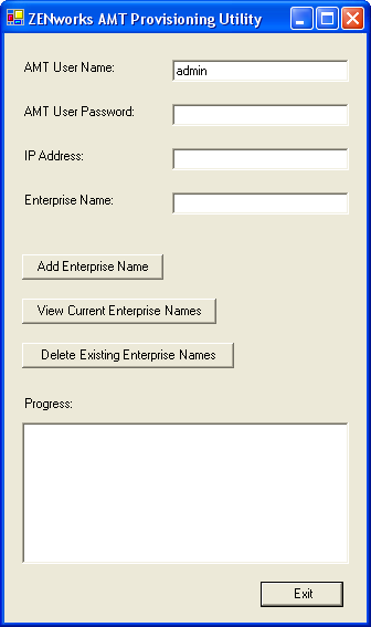
This must be run on a different device than is being provisioned.
-
Fill in the fields:
-
Enter the appropriate administrator account and passwords in their respective fields.
This is the same as you entered in Step 2.
-
Enter the currently valid IP address for the device.
-
Enter an enterprise name.
Intel suggests that the enterprise name be chosen to indicate the device’s general location. For example, all the devices in the home office may be given an enterprise name of “Company_HQ,” and all devices in field offices may be given enterprise names reflecting their geographical locations.
While it is not required, it is assumed that large numbers of devices will have the same enterprise name. Each AMT device itself may have up to four different enterprise names.
You can use the or the to manage the names in the list box.
-
-
Select , then click .
This adds the defined enterprise name into the list box and to the device.
-
Repeat Step 1 through Step 8 for each device to be provisioned with the Small Business mode.
-
To provide the provisioned enterprise names to ZENworks Linux Management, continue with Setting Up the Global Intel AMT Enterprise Names.
Setting Up the Global Intel AMT Enterprise Names
The Intel AMT functionality allows you to accurately identify devices, even if they have had physical drive replacements. This sets up Preboot Services with persistent device identification by providing ZENworks with nonvolatile memory for storing the unique device identity.
For more information, see Section 28.3.7, Intel Active Management Technology (AMT).
To configure Intel AMT for Preboot Services:
-
In the ZENworks Control Center, click the tab, which displays the following Management Zone Settings section:
-
In this section, click to display the configuration sections.
-
Locate the Intel Active Management Technology (AMT) section:
-
Fill in the fields:
Name list: Enterprise names are given to AMT devices when they are provisioned. This list should contain at least one valid AMT enterprise name for every AMT device in the ZENworks Management Zone. Click to place each one into the list box.
Move up/Move down: Arranges the order in which the AMT names are listed. You can move only one at a time.
Remove: To remove a name from the list, select the name, then click .
-
Click either or to save the changes